Spellman High Voltage Electronics Limited - Company Confidential
This document must not be copied or distributed without express permission from Spellman High Voltage Electronics Limited
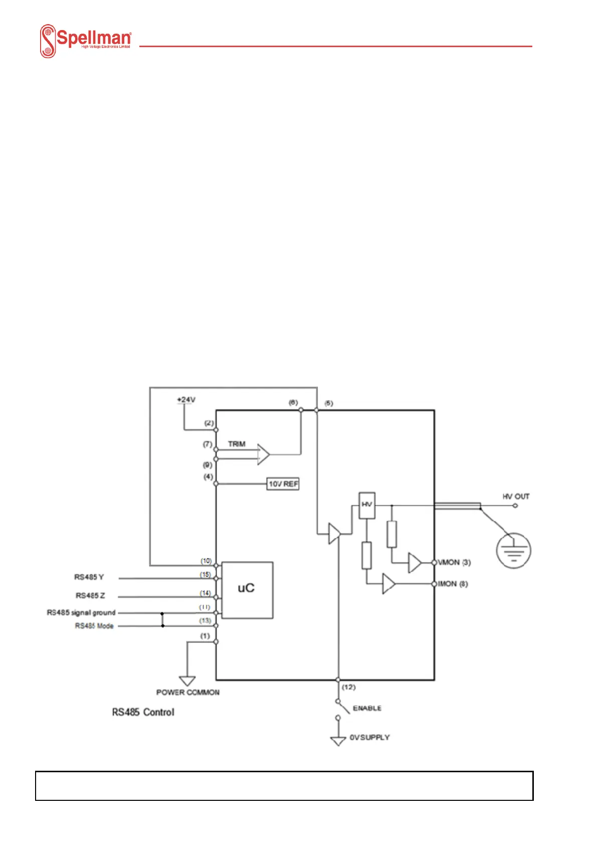
4.2.2 RS485 Connection
The unit has RS485 communication facilities available via pins 14 and 15 of the 15 way ‘D’
connector. For the protocol used, refer to protocol document 48113-21, which can be
provided on request.
The unit may be controlled digitally as follows: -
24V Power input on Pin 2.
Ground on Pin 1.
Select Mode RS485 – connected Power common to Pin 1.
RS485 signal ground on Pin 11.
RS485 Z (inverting) on Pin 14 – connect to RS485 inverting pin, Z or B on PC
RS485 Y (non-inverting) on Pin 15 – connect to RS485 non-inverting pin, Y or A on PC. A
120R termination resistor should be fitted to the last MPD particularly if long cabling is
used.
Connect Enable Pin 12 to ground to enable HV output. This is independent of the
firmware/communications interface and can be used to shut-down the HV output.
Connect Pin 5 to 10 and link Pin 11 to 13.