ST/STR/STA MANUAL 16 118107-001 REV J
Toggle to reset latched faults, Ground = Inhibit, Open = HIGH VOLTAGE ON
+24Vdc @ open, <25mA @ closed
External Interlock Return
Return for External Interlock. Pins 3 and 4 must be connected to HV enable
0-10Vdc = 0-100% rated output, Zout = 1kΩ, 1%
0-10Vdc = 0-100% rated output, Zout = 1kΩ, 1%
0-10Vdc = 0-100% rated output, Zin =>10MΩ, jump to pin 8 for local control
0-10Vdc = 0-100% rated output, front panel potentiometer
0-10Vdc = 0-100% rated output, Zin =>10MΩ, jump to pin 11 for local control
0-10Vdc = 0-100% rated output, front panel potentiometer
24Vdc @ open, 2A peak, 1A DC @ closed
Return for Remote Power On
+24Vdc @ open, 2A peak, 1A DC @ closed, connect to pin 15 for front panel
operation
+24Vdc @ open, 2A peak, 1A DC @ closed, momentarily connect to pin 15 for
HV enable
HIGH VOLTAGE OFFIndicator
HIGH VOLTAGE ON Indicator
+24Vdc @ 25mA = HIGH VOLTAGE ON
Open collector, Low = Active, 35V maximum @ 10mA
Open collector, Low = Active, 35V maximum @ 10mA
Open collector, Low = Active, 35V maximum @ 10mA
Open collector, Low = Active, 35V maximum @ 10mA
0-10Vdc = 0-100% rated output, Zout = 5kΩ, 1%
Remote Overvoltage Adjust
0-10Vdc = 0-105% rated output
Open collector, Low = Active, 35V maximum @ 10mA
Open collector, Low = Active, 35V maximum @ 10mA
Open collector, Low = Active, 35V maximum @ 10mA
Open collector, Low = Active, 35V maximum @ 10mA
Open collector, Low = Active, 35V maximum @ 10mA
Open collector, Low = Active, 35V maximum @ 10mA
Open collector, Low = Active, 35V maximum @ 10mA
Open collector, Low = Active, 35V maximum @ 10mA
Remote Power Program Input
0-10Vdc = 0-100% rated output, Zout = 1kΩ, 1%, jump to pin 43 for local control
Local Power Program Output
0-10Vdc = 0-100% rated output, internal potentiometer
= Denotes jumper connection for simplified local front panel control
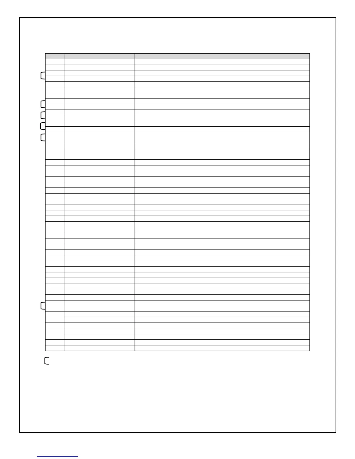
Figure 3.10 JB1 Rear Panel Interface Connecter
 Loading...