101501-565 Rev C Page 4 of 58
The necessary connections for the RS-232 interface are on pins 47, 48 and 49.
3.2 ETHERNET INTERFACE
The Ethernet interface has the following attributes:
10/100-Base-T
IP address can be set by the system integrator (Default Address:
192.168.1.4)
Network Mask can be set by the system integrator (Default Mask:
255.255.255.0)
TCP Port Number can be set by the system integrator (Default Port:
50000)
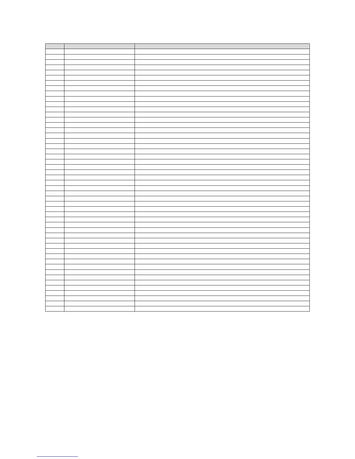
Pin Signal Parameters
1 Power Supply Common Power Supply Ground
2 Reset/HV Inhibit Toggle to reset latched faults, Ground = Inhibit, Open = HV ON
3 External Interlock +24Vdc @ open, <25mA @ closed
4 External Interlock Return Return for External Interlock. Pins 3 and 4 must be connected to HV enable
5 mA Test Point 0-10Vdc = 0-100% rated output, Zout = 1kΩ, 1%
6 kV Test Point 0-10Vdc = 0-100% rated output, Zout = 1kΩ, 1%
7 +10Vdc Reference +10Vdc @ 1mA
8 mA Program Input 0-10Vdc = 0-100% rated output, Zin =>10MΩ, jump to pin 8 for local control
9 Local mA Program Output 0-10Vdc = 0-100% rated output, front panel potentiometer
10 kV Program Input 0-10Vdc = 0-100% rated output, Zin =>10MΩ, jump to pin 11 for local control
11 Local kV Program Output 0-10Vdc = 0-100% rated output, front panel potentiometer
12 Remote Power On Output 24Vdc @ open, <25mA @ closed
13 Remote Power On Return Return for Remote Power On
14 Remote HV OFF +24Vdc @ open, <25mA @ closed, connect to pin 15 for front panel operation
15 Remote HV OFF/ON Common Remote HV OFF/ON Common
16 Remote HV ON +24Vdc @ open, <25mA @ closed, momentarily connect to pin 15 for HV enable
17 HV OFF Indicator +24Vdc @ 25mA = HV OFF
18 HV ON Indicator +24Vdc @ 25mA = HV ON
19 Power Supply Common Power Supply Ground
20 +24Vdc Output +24Vdc @ 100mA, maximum
21 Voltage Mode Status Open collector, Low = Active, 35V maximum @ 10mA
22 Current Mode Status Open collector, Low = Active, 35V maximum @ 10mA
23 Power Mode Status Open collector, Low = Active, 35V maximum @ 10mA
24 Interlock Closed Status Open collector, Low = Active, 35V maximum @ 10mA
25 Power Test Point 0-10Vdc = 0-100% rated output, Zout = 5kΩ, 1%
26 Spare
27 Spare
28 Remote Overvoltage Adjust 0-10Vdc = 0-105% rated output
29 Over Power Fault Open collector, Low = Active, 35V maximum @ 10mA
30 Over Voltage Fault Open collector, Low = Active, 35V maximum @ 10mA
31 Over Current Fault Open collector, Low = Active, 35V maximum @ 10mA
32 System Fault Open collector, Low = Active, 35V maximum @ 10mA
33 RGLT Error Fault Open collector, Low = Active, 35V maximum @ 10mA
34 ARC Open collector, Low = Active, 35V maximum @ 10mA
35 Over Temp Fault Open collector, Low = Active, 35V maximum @ 10mA
36 AC Fault Open collector, Low = Active, 35V maximum @ 10mA
37 Spare
38 Spare
39 Spare
40 Spare
41 Spare
42 Remote Power Program Input 0-10Vdc = 0-100% rated output, Zout = 1kΩ, 1%, jump to pin 43 for local control
43 Local Power Program Output 0-10Vdc = 0-100% rated output, internal potentiometer
44 +5Vdc Output +5Vdc @ 100mA, maximum
45 +15Vdc Output +15Vdc @ 100mA, maximum
46 -15Vdc Output -15Vdc @ 10mA, maximum
47 RS-232 Tx RS-232 Tx
48 RS-232 Rx RS-232 Rx
49 RS-232 GND RS-232 GND
50 Power Supply Common Power Supply Ground
 Loading...