101501-565 Rev C Page 5 of 58
RJ-45 connector
Network attachment via Crossover and Standard Ethernet cables.
Supported Operating Systems: Windows 98 2ED, Windows 2000
(SP2), Windows NT (SP6), Windows XP Professional
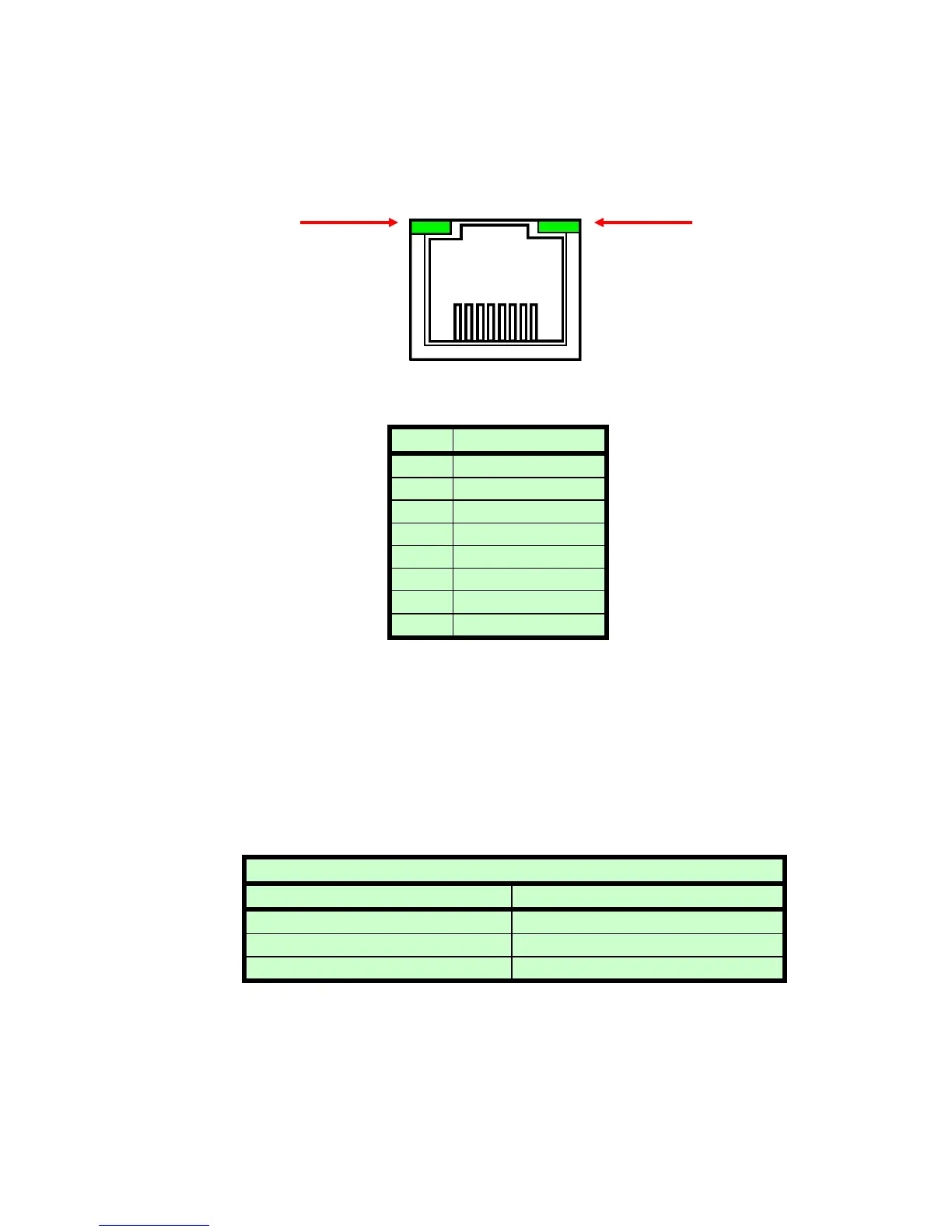
Figure 2 – JB9, Ethernet RJ45 Jack (front view)
PIN DESCRIPTION
1 TX+
2 TX-
3 RX+
4 -
5 -
6 RX-
7 -
8 -
The Ethernet RJ-45 has two LED indicators, as shown in Figure 2. The left
LED, LED1 indicates that the network processor has a valid network link.
The right LED, LED2 indicates network activity.
3.3 RS-232 CABLING
A shielded cable is used to connect the ST serial port through the 50 pin
breakout to the serial port on a standard personal computer. Please refer
to the following chart.
3.4 ETHERNET CABLING
Shielded Category 5 (CAT5) Ethernet patch cables are used to connect
the ST to the host computer. There are two ways to connect to the ST
PC to ST Board Cable Details
PC Connector (DB-9 Female) ST Connector (DB-50 male)
Pin 2: TX from ST to PC Pin 47: TX from ST to PC
Pin 3: RX to ST from PC Pin 48: RX to ST from PC
Pin 5: Ground Pin 49: Ground
8 7 6 5 4 3 2 1
LED 1 LED 2
 Loading...