20
21
22
23
24
25
26
27
28
29
30
31
32
33
34
35
36
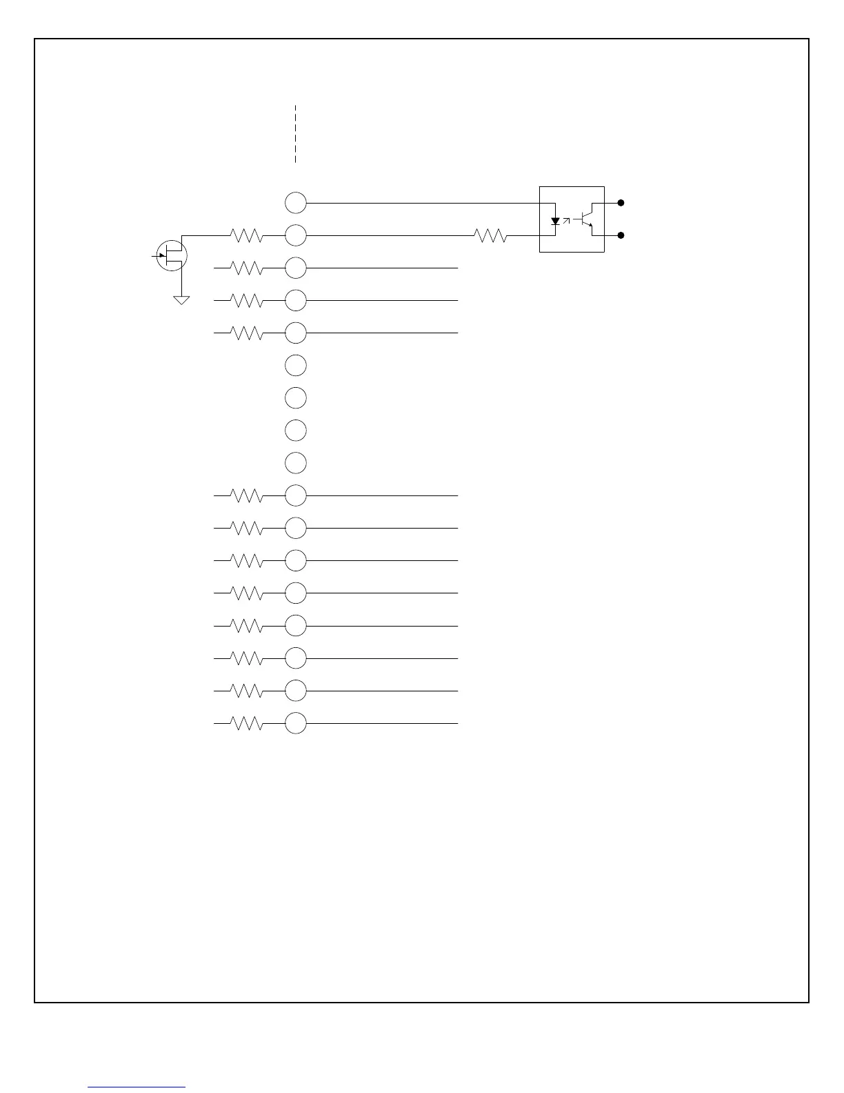
+24Vdc @ 100mA, maximum
Voltage Mode Status
Current Mode Status
Power Mode Status
Interlock Closed Status
Over Power Fault
Over Voltage Fault
Over Current Fault
System Fault
RGLT Error Fault
ARC
Over Temp Fault
AC Fault
General Purpose
Optocoupler
JB1 Rear Panel
100Ω
100Ω
100Ω
100Ω
100Ω
100Ω
100Ω
100Ω
100Ω
100Ω
100Ω
100Ω
R Limit
Signals are 35Vdc @ 10mA, maximum.
R Limit must be selected to limit current ≤ 10mA.
Power Supply
Internal Circuitry
Customer
External Circuitry
All cables should be shielded with the
shields returned to chassis ground (E1) of
the high voltage power supply.
24Vdc lamps or relays may replace the
optocouplers shown. Whatever devices
employed they should be located as close as
possible to the high voltage power supply.
 Loading...