270M
Rapid
Scanning Imaging Spectrograph
3 Electrical Connections:
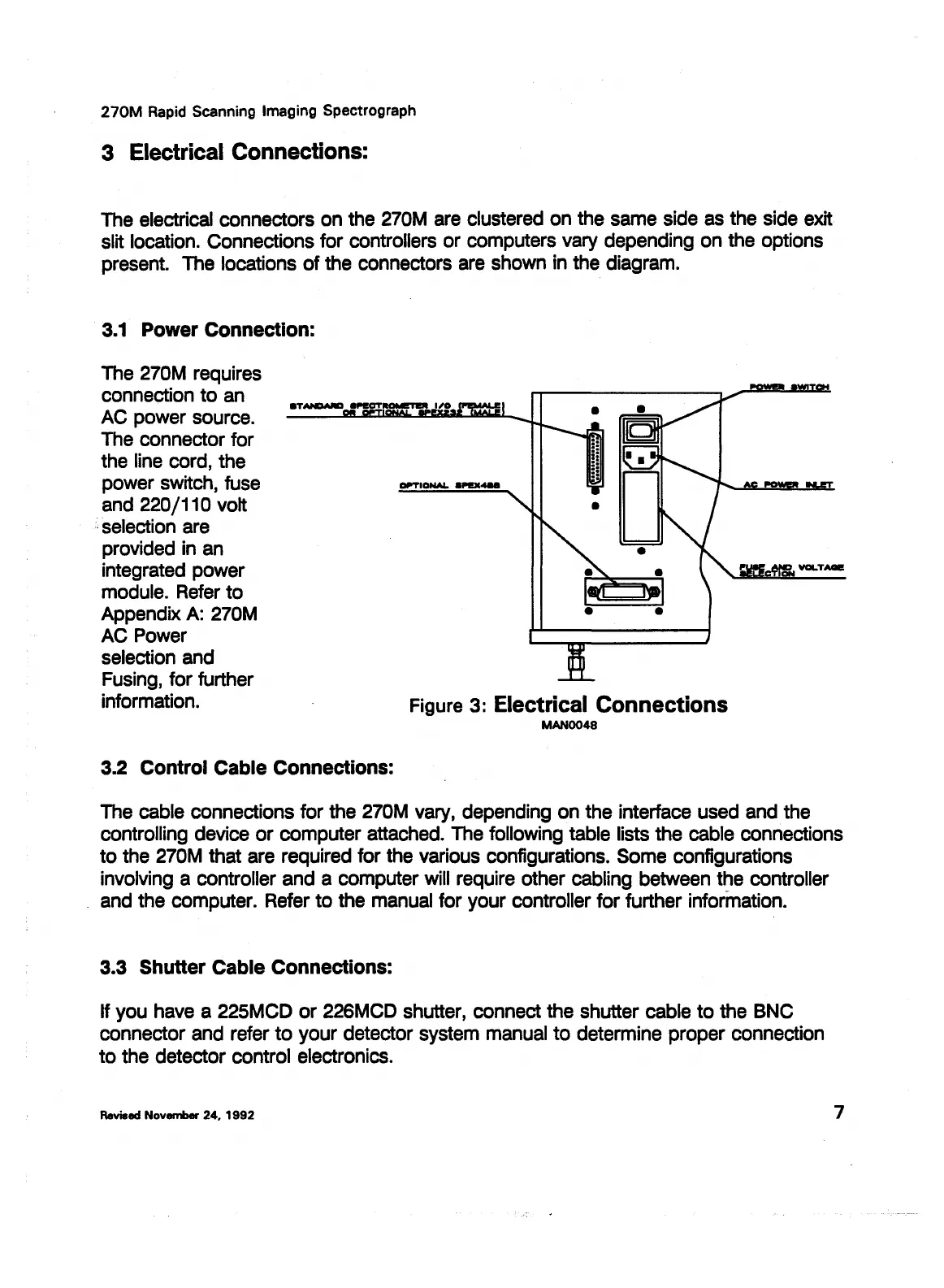
The electrical connectors on the 270M are clustered on the same side as the side exit
slit location. Connections for controllers
or
computers vary depending on the options
present. The locations
of
the connectors are shown in the diagram.
3.1
Power Connection:
The 270M requires
connection
to
an
AC power source.
The connector for
the line cord, the
power switch, fuse
and 220/110 volt
, selection are
provided in an
integrated power
module. Refer
to
Appendix
A:
270M
AC Power
selection and
Fusing, for further
information.
3.2 Control Cable Connections:
Figure 3: Electrical Connections
MAN0048
The cable connections for the 270M vary, depending on the interface used and the
controlling device
or
computer attached. The following table lists the cable connections
to
the 270M that are required for the various configurations. Some configurations
involving a controller and a computer will require other cabling between the controller
and the computer. Refer
to
the manual for your controller for further information.
3.3 Shutter Cable Connections:
If you have a 225MCD
or
226MCD shutter, connect the shutter cable
to
the BNC
connector and refer
to
your detector system manual
to
determine proper connection
to
the detector control electronics.
Revised
November
24,
1992
7
Leica Microsystems, Inc.'s Ex. 1033