270M
Rapid
Scanning Imaging Spectrograph
Appendix
B:
270M
Interface Connector
Pin
Assignments
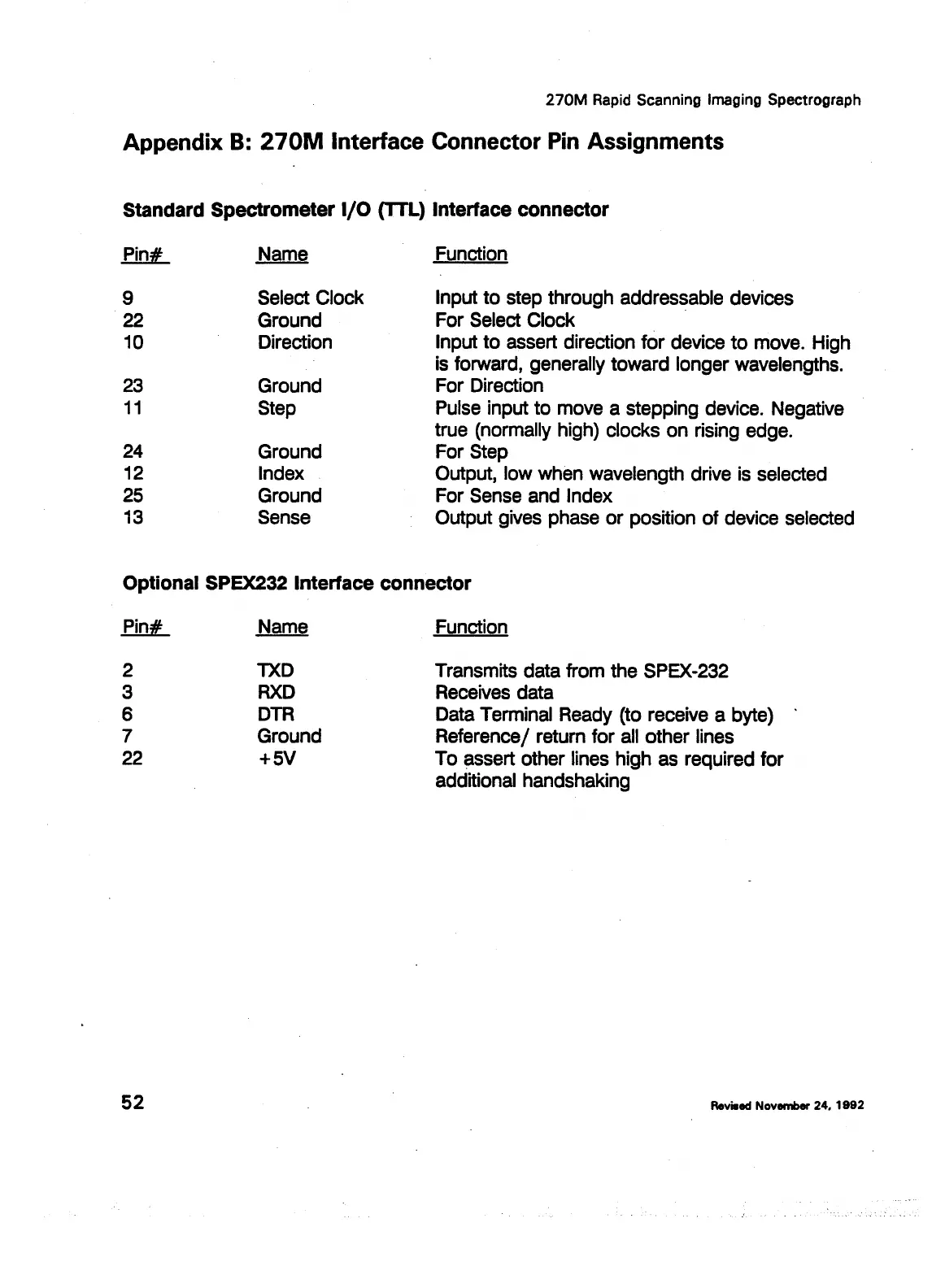
Standard
Spectrometer
1/0
(TTL}
Interface
connector
Pin#
Name
9
Select Clock
22 Ground
10 Direction
23
Ground
11
Step
24
Ground
12 Index
25
Ground
13
Sense
Function
Input to step through addressable devices
For Select Clock ·
Input to assert direction for device
to
move. High
is forward, generally toward longer wavelengths.
For Direction
Pulse input to move a stepping device. Negative
true (normally high) clocks on rising edge.
For Step
Output, low when wavelength drive is selected
For Sense and Index
Output gives phase or position of device selected
Optional
SPEX232
Interface
connector
Pin#
2
3
6
7
22
52
Name
TXD
RXD
DTR
Ground
+SV
Function
Transmits data from the SPEX-232
Receives data
Data Terminal Ready (to receive a byte)
Reference/ return for
all
other lines
To assert other lines high as required for
additional handshaking
Reviaed November
24,
1992
Leica Microsystems, Inc.'s Ex. 1033