Not to be distributed without prior consent of SPI Lasers UK Ltd.
Slide: 12
FS-S00149-Rev A
Customer Requirements Pre Install
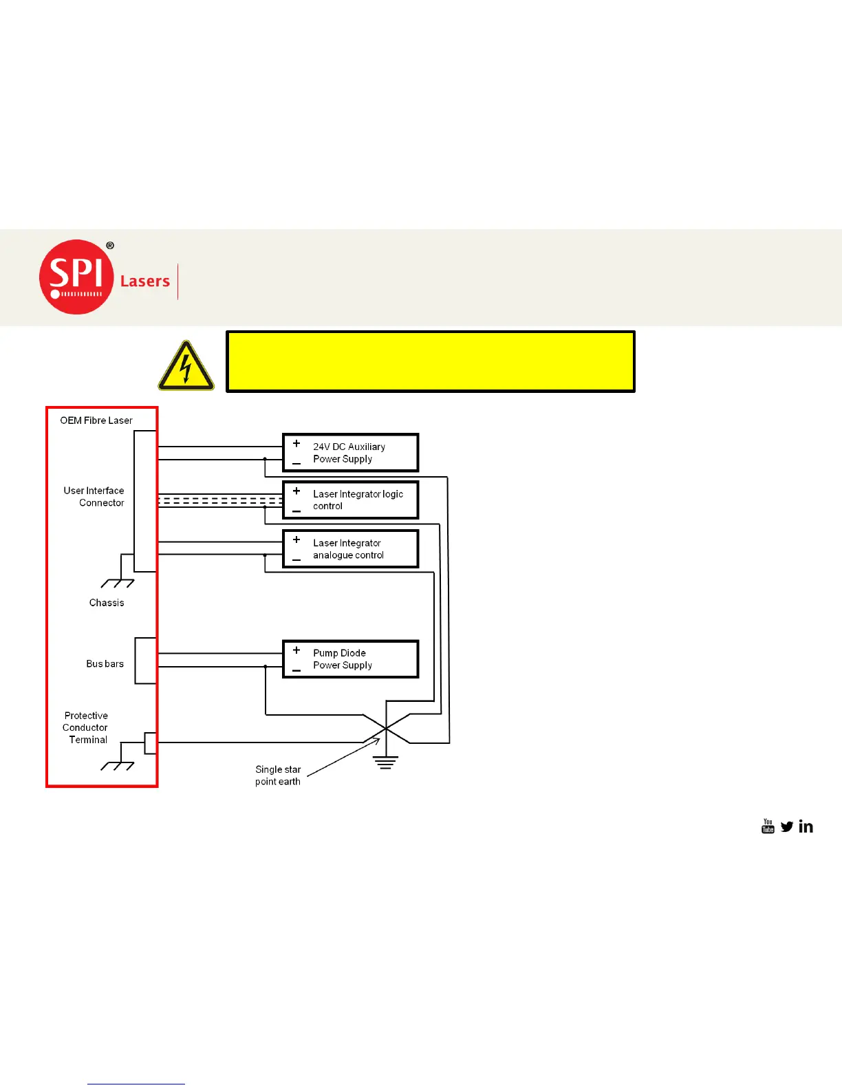
Protective Conductor (Earth)Terminals
29/06/2016
37 Way Dsub connector provides the input
for the following supplies.
• External 24VDC Aux PSU
• Input /output Logic controls from external
PLC/CNC controller.
• Analogue Control Inputs
All of the above must be connected on the
negative side of the circuit to chassis Ground
single star point.
37 way Dsub Connector
The Bus Bars for the DC input power supply
must be connected from Negative to
Machine chassis Ground Single star point
The Final and most important connection is
the Prism OEM chassis to the Machine
chassis Ground. Leaving this open may
cause the other signals to float due to
insufficient return path to the chassis ground
and closing the ground loop.
For safe operation of the Prism OEM Laser and to comply with
regional electrical codes, grounding of the machine and
equipment is of the highest importance!
 Loading...