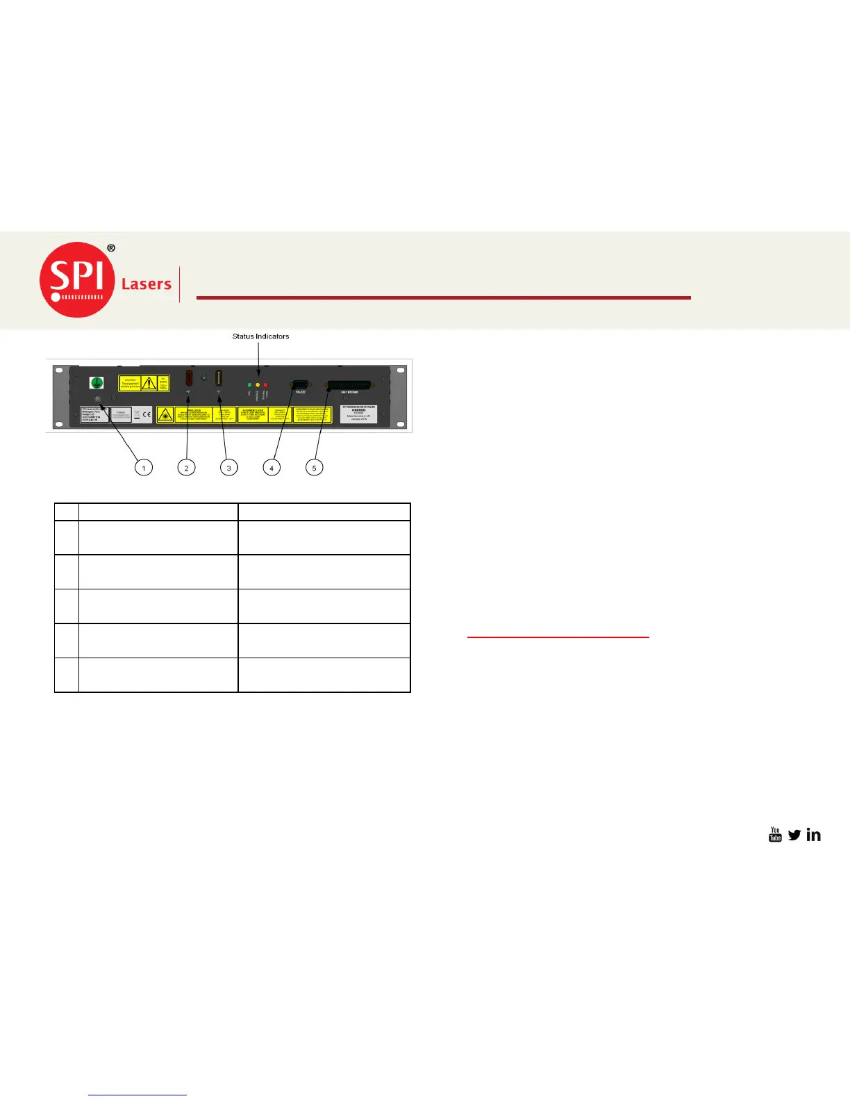
EasyManua.ls Logo

SPI Lasers redPOWER - Electrical Connections to Laser

SPI Lasers redPOWER
19 pages
Print Icon
To Next Page IconTo Next Page
To Previous Page IconTo Previous Page
Loading...
Not to be distributed without prior consent of SPI Lasers UK Ltd.
Slide: 16
FS-S00149-Rev A
Electrical Connections to Laser
29/06/2016
Function
Connector Description
1
Protective Conductor
(Earth) Terminal
M5 female thread
2
Pump Diode PSU +V
Bus Bar with two eyes for
M8 bolts
3
Pump Diode PSU -V
Bus Bar with two eyes for
M8 bolts
4
RS-232 and RS-485
9-way D-Type male
connector
5
User Interface
37-way D-type male
connector
Connect the protective earth from Item 1 to machine
chassis ground.
Connect the power supply Negative cable Item 3.
Ensure the negative terminal of the power supply is
also connected to chassis ground
Connect the power supply Positive Cable Item 2.
Connect RS232/485 Cable to item 4. Can be used to
monitor the Prism unit using the Prism GUI
Provided.
Connect the 37 Way Dsub connector Item 5 for input
and output signals, 24V control supply to laser.
Connect BDO to Process Head ensuring the BDO is
locked in to position.
Once all of the above is taken care of go to
start up/Shutdown procedure

Related product manuals