www.modellmarkt24.ch
2.2 Controllers connecting SPIN 125 opto, SPIN 200 opto and SPIN 300 opto:
This controllers contains ancillary circuit which avoids sparking when the controller
is being connected to accumulators.
Controller connecting procedure:
1) connect minus pole of controller to minus pole of accumulator
2) connect red thin wire (1,5 mm2) to plus pole of accumulator
3) connect plus pole of controller to plus pole of accumulator
4) disconnect red thin wire (1,5 mm2) to plus pole of accumulator
•
•
•
the distance between motor and controller should not exceed 10-15 cm. Flight battery
cables can be extended to 20-25 cm. A further prolongation of the driving battery cables
can be achieved by connecting in parallel to the cables electrolytic capacitors (with low
internal resistance, so called low ESR capacitors with appropriate voltage capability and a
capacity of several hundred microfarad), one capacitor per 25 cm cable length is
necessary.
connect the JR connector to the throttle channel of the receiver.
Plug-in the JR plug (red plug) into the receiver of the duplex-EX system (or into the
EXPANDER).
Once the main power pack is connected, handle the model with
extreme care – ensure that everyone is well clear of the propeller all
the time!!!
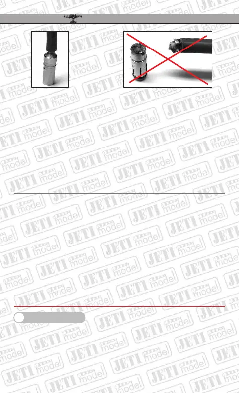
good soldered connector
bad soldered connector
3. Online Telemetry
(not valid for controllers SPIN PRO 11, 22 and 33)
With the aid of the JetiBox the controllers SPIN PRO provide the possibility of depicting
the controller status in real time. The JR plug with red body can be connected directly to
theJetiBox or to the input EXT. of the DUPLEX 2,4GHz receiver.
The controller parameter set-up with the aid of the JetiBox can be carried out only if the JR
plug (throttle) is disconnected from the receiver (or the receiver is switched-off). If the
EN
SPIN SPIN
PROPRO
19
www.modellmarkt24.ch