IM-P344-01 CTLS Issue 4
IM-P344-01 CTLS Issue 4
26
27
AEL3 Electric Linear Actuators AEL3 Electric Linear Actuators
................
................
T15
3
1
55
°C
-10
131
°F
14
5-95%RH
100-110 V~
230 V~
................
................
T15
3
1
55
°C
-10
131
°F
14
5-95%RH
100-110 V~
230 V~
1x 3x 1x
Fig. 29
T15
1
2.1
2.2
3.1
3.2
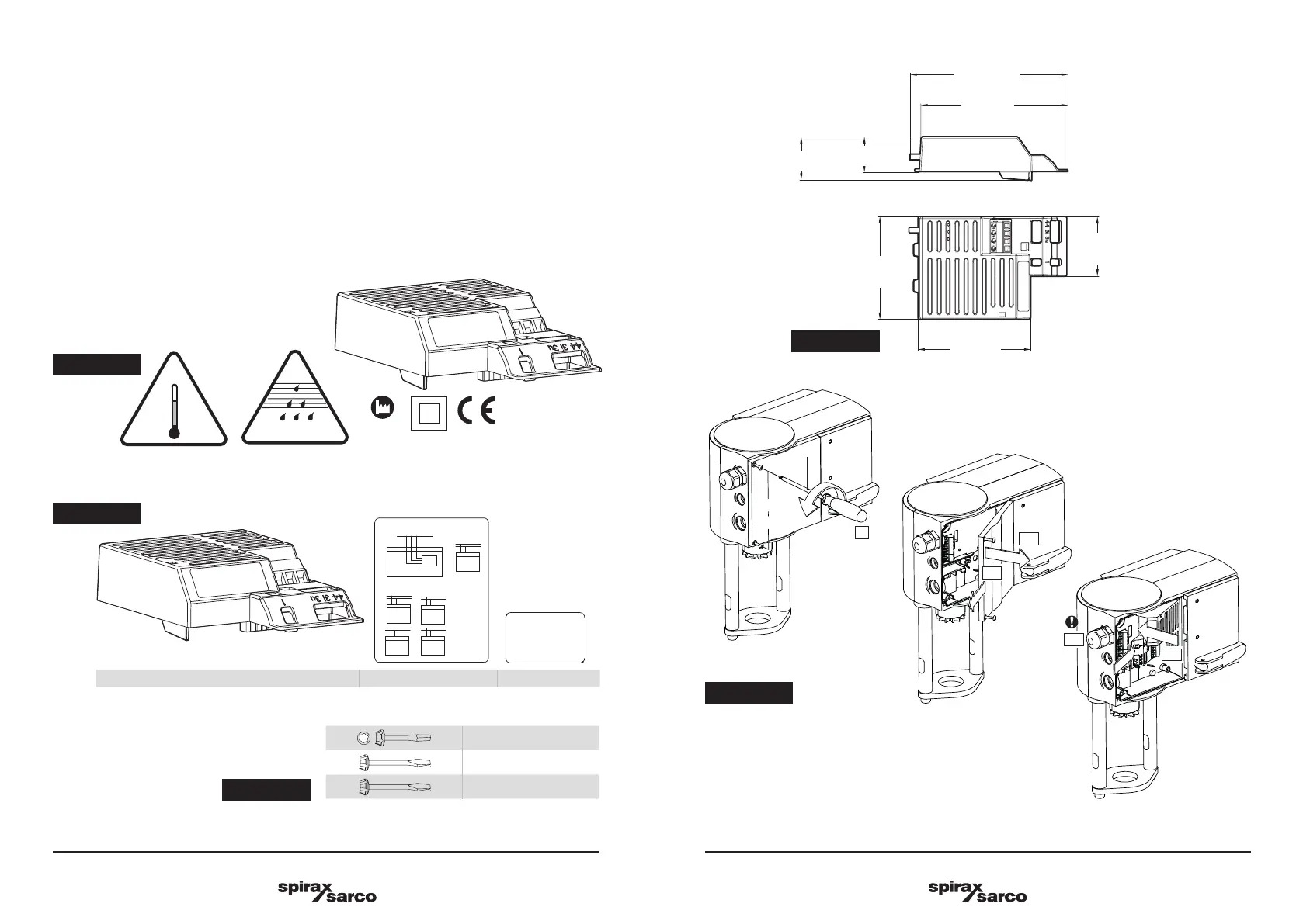
3.7 100 V and 230 V power module installation
There are 2 additional options available for power supply: 100-110 V and 230 V. These are available by
connecting an auxiliary power module to the standard actuator model. Fresh labels are provided that reflect
the change made.
1. Open the actuator cover.
2. Slot in the appropriate power module in the space provided.
3. Replace/cover the original 24V wiring label on the inside of the actuator removable housing cover with
fresh power module wiring label.
4. Use provided power module marking label and affix it on the existing label located on the underside of
the actuator housing, so that it covers the existing portion of the label containing 24V and UL markings,
as shown below.
Guidelines for the electrician
Fig. 27
Fig. 28
Fig. 29
Fig. 30
105.3 mm
99 mm
75 mm
68.4
mm
23.5 mm
29.3 mm
39.8
mm
Fig. 31
 Loading...