7
3.568.5275.906
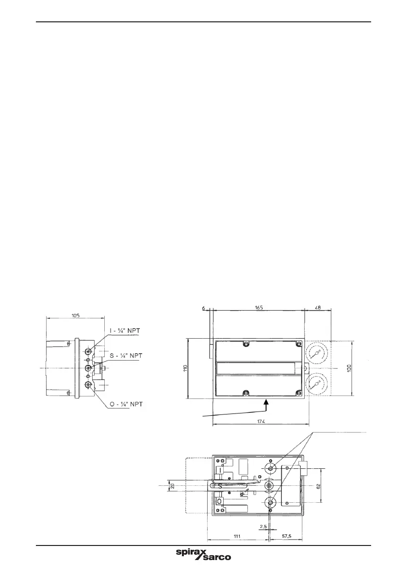
S:
Entrata aria di alimentazione
Air supply inlet
I:
Entrata segnale regolante
Control signal inlet
O:
Uscita segnale comando valvola
Output signal to the actuator
Fig. 2
Ø M8:
Fori attacco staa
Attachment bracket
holes
Scarico Convogliato
Direct Exhaust
¼" NPT
B - MOUNTING OF POSITIONER ON
THE VALVE (Fig. 4, 5 and 6)
The PP 5 positioner is generally supplied already
mounted on valve yoke and duly connected to
the pneumatic actuator.
Using the correct mounting accessories, it may
be easily installed on dierent types of valves
having actuators conforming to the Namur
standard.
Follow the instructions below:
1) Fix the sliding pin holder plate (A) to the valve
stem coupling block (Fig. 4-8).
2) Fix the mounting plate (C) to the positioner
using the two screws M8: The position of the
positioner on the plate must be according to the
size (width of the control valve yoke: the screws
and the xing point must be located to an ideal
distance of 45-50 mm from the axis of the valve
stem (see Fig. 5). For this reason the xing
holes 1 or 2, 3, 4 must be chosen according to
the yoke measurement D. With standard valves
the xing hole is normally the number 1 but with
wider yokes the xing point will be proportionally
moved to holes 2 or 3 or 4 to keep the xing
distance from the axis within the ideal values.
3) Screw and x the sliding pin on its plate after
having determined the hole to be used (R-S-T)
according to the valve stroke; make reference
to Fig. 5.
B - MONTAGGIO DEL POSIZIONATORE
SULLA VALVOLA (Fig. 4, 5 e 6)
Il posizionatore PP 5 viene normalmente
fornito già montato sul castello della valvola
ed opportunamente collegato alla testata
pneumatica. Impiegando gli opportuni accessori
di montaggio può essere facilmente applicato
su valvole di vario tipo che abbiano attuatori a
membrana costruiti secondo normativa Namur.
Agire nel seguente modo:
1) Fissare la piastrina porta perno di scorrimento
(A) al blocchetto di accoppiamento dello stelo
della valvola (riferirsi a Fig. 4 - 8).
2) Fissare la staa di montaggio C al posizionatore
utilizzando le apposite due viti M 8. La posizione
delle viti sulla staa dipende dalla larghezza
del castello della valvola di controllo: esse
dovranno trovarsi a montaggio ultimato
ad una distanza ideale di circa 45-50 mm
dall’asse stelo (vedere Fig. 5). Verranno
pertanto utilizzati i fori 1-2-3 o 4 in funzione
della dimensione D della valvola. Per valvole
standard il punto di ssaggio è il foro 1; con
castelli più larghi il punto di ssaggio si sposterà
proporzionalmente verso il foro 4 con lo scopo
di mantenere entro i limiti la quota ideale.
3) Fissare il perno di scorrimento (B) alla relativa
piastrina scegliendo la posizione (R-S-T) che,
avendo rispettato la “quota ideale”, è deducibile dalla
tabella di Fig. 5 in funzione della corsa di valvola.
 Loading...