8
SX80/90
8 IM-P323-35: Part No 3231354 Issue 7.0 Feb-13
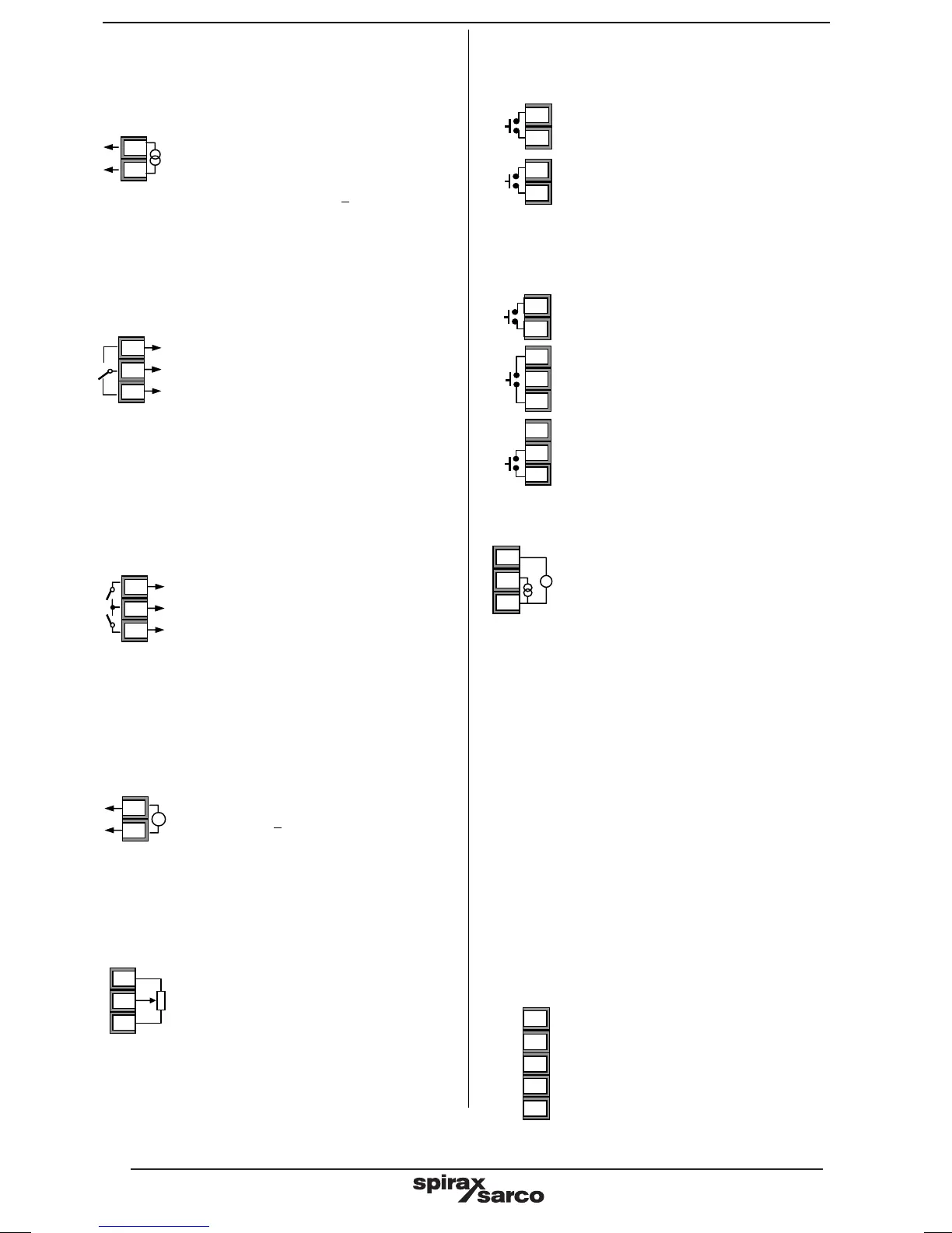
2.10 Output 3 (OP3) 4-20mA - SX90 only
OP3 is a 4-20mA analogue output in SX90 only.
For functionality see Quick Code Set 2.
• Isolated output 300Vac CATII
• Configurable 0-20mA or 4-20mA
• Max load resistance: 500Ω
• Calibration accuracy: < +(1% of reading
+200μA)
2.11 Output 4 (OP4) - SX90 only
Output 4 is a changeover (Form C) relay fitted in SX90 only.
For functionality see Quick Start Code.
• Isolated output 300Vac CATII
• Contact rating: 2A 264Vac resistive
2.12 Outputs 5 & 6 (OP5/6) - SX90 only
Outputs 5 and 6 are supplied as normally open (Form A)
relays and are to control motor driven valves.
They share a common connection and are, therefore, not
isolated from each other.
For alarm type see Quick Code Set 3.
• Isolated output 300Vac CATII
• Contact rating: 2A 264Vac resistive - any
terminal limited to 2A
2.13 Transmitter Power Supply- SX90
only
The transmitter power supply provides an 24V supply to
power an external transmitter.
• Isolated output 300Vac CATII
• Output 24V +10%, 30mA
2.14 Potentiometer Input - SX90 only
The potentiometer input provides feedback of the valve
position
• Potentiometer resistance: 100-10kΩ
• Excitation voltage: 0.46 to 0.54V
• Short circuit detection: <25Ω
• Open circuit detection: >2MΩ
• Open circuit wiper detection >5MΩ
2.15 Digital Inputs A & B – SX80 only
These are contact closure inputs which may be configured for
functions listed in section 9.1.11.
• Switching:
LA 12Vdc at 12mA max
LB 12Vdc at 40mA
• Contact open > 1200Ω.
• Contact closed < 300Ω
2.16 Digital Inputs B. C & D - SX90 only
These are contact closure inputs which may be configured for
functions listed in section 9.1.11.
• Not isolated from the sensor input
• LC and LD not isolated from each other
• Switching:
• LC/LD 12Vdc at 6mA max
• LB 12Vdc at 12mA
• Contact open > 1200Ω. Contact closed <
300Ω
2.17 Remote Setpoint Input - SX90 only
• There are two inputs; 4-20mA and 0-10
Volts which can be fitted in place of digital
communications
• It is not necessary to fit an external burden
resistor to the 4-20mA input
• If the 4-20mA remote setpoint input is connected and valid
(>3.5mA; < 22mA) it will be used as the main setpoint (if
configured). If it is not valid or not connected the
controller will try to use the Volts input. Volts sensor
break occurs at <-1; >+11V. The two inputs are not
isolated from each other
• If neither remote input is valid the controller will fall back
to the internal setpoint, SP1 or SP2 and flash the alarm
beacon. The alarm can also be configured to activate a
relay (see section 12.1.1) or read over digital
communications.
• To calibrate the remote setpoint, if required, see section
16.5.4
• A local SP trim value is available in access level 3 (see
section 10.1).
• Isolated 300Vac CATII.
2.18 Digital Communications - SX90 only
Digital communications uses Modbus protocol. It is
available in SX90 only as EIA422 (EIA485 5-wire).
• EIA422 (5-wire)
• Isolated 300Vac CATII.
RV
RI
RC
V
I
AA
AB
AC
Rx+
Rx-
Com.
Tx+
Tx-
HB
HC
HD
HE
HF
5A
5B
5C
OP6
3A
3B
+
-
V
+
-
3C
3D
PH
PW
PL
D
4A
4C
4B
B
LB
LC
C
4A
4C
4B
B
LB
LC
A
LA
LC
SX80/90
8 IM-P323-35: Part No 3231354 Issue 7.0 Feb-13
2.10 Output 3 (OP3) 4-20mA - SX90 only
OP3 is a 4-20mA analogue output in SX90 only.
For functionality see Quick Code Set 2.
• Isolated output 300Vac CATII
• Configurable 0-20mA or 4-20mA
• Max load resistance: 500Ω
• Calibration accuracy: < +(1% of reading
+200μA)
2.11 Output 4 (OP4) - SX90 only
Output 4 is a changeover (Form C) relay fitted in SX90 only.
For functionality see Quick Start Code.
• Isolated output 300Vac CATII
• Contact rating: 2A 264Vac resistive
2.12 Outputs 5 & 6 (OP5/6) - SX90 only
Outputs 5 and 6 are supplied as normally open (Form A)
relays and are to control motor driven valves.
They share a common connection and are, therefore, not
isolated from each other.
For alarm type see Quick Code Set 3.
• Isolated output 300Vac CATII
• Contact rating: 2A 264Vac resistive - any
terminal limited to 2A
2.13 Transmitter Power Supply- SX90
only
The transmitter power supply provides an 24V supply to
power an external transmitter.
• Isolated output 300Vac CATII
• Output 24V +10%, 30mA
2.14 Potentiometer Input - SX90 only
The potentiometer input provides feedback of the valve
position
• Potentiometer resistance: 100-10kΩ
• Excitation voltage: 0.46 to 0.54V
• Short circuit detection: <25Ω
• Open circuit detection: >2MΩ
• Open circuit wiper detection >5MΩ
2.15 Digital Inputs A & B – SX80 only
These are contact closure inputs which may be configured for
functions listed in section 9.1.11.
• Switching:
LA 12Vdc at 12mA max
LB 12Vdc at 40mA
• Contact open > 1200Ω.
• Contact closed < 300Ω
2.16 Digital Inputs B. C & D - SX90 only
These are contact closure inputs which may be configured for
functions listed in section 9.1.11.
• Not isolated from the sensor input
• LC and LD not isolated from each other
• Switching:
• LC/LD 12Vdc at 6mA max
• LB 12Vdc at 12mA
• Contact open > 1200Ω. Contact closed <
300Ω
2.17 Remote Setpoint Input - SX90 only
• There are two inputs; 4-20mA and 0-10
Volts which can be fitted in place of digital
communications
• It is not necessary to fit an external burden
resistor to the 4-20mA input
• If the 4-20mA remote setpoint input is connected and valid
(>3.5mA; < 22mA) it will be used as the main setpoint (if
configured). If it is not valid or not connected the
controller will try to use the Volts input. Volts sensor
break occurs at <-1; >+11V. The two inputs are not
isolated from each other
• If neither remote input is valid the controller will fall back
to the internal setpoint, SP1 or SP2 and flash the alarm
beacon. The alarm can also be configured to activate a
relay (see section 12.1.1) or read over digital
communications.
• To calibrate the remote setpoint, if required, see section
16.5.4
• A local SP trim value is available in access level 3 (see
section 10.1).
• Isolated 300Vac CATII.
2.18 Digital Communications - SX90 only
Digital communications uses Modbus protocol. It is
available in SX90 only as EIA422 (EIA485 5-wire).
• EIA422 (5-wire)
• Isolated 300Vac CATII.
RV
RI
RC
V
I
AA
AB
AC
Rx+
Rx-
Com.
Tx+
Tx-
HB
HC
HD
HE
HF
5A
5B
5C
OP6
3A
3B
+
-
V
+
-
3C
3D
PH
PW
PL
D
4A
4C
4B
B
LB
LC
C
4A
4C
4B
B
LB
LC
A
LA
LC
 Loading...