IM-P192-02 MI Issue 246
4.14.2 Alarm status register bit-fields:
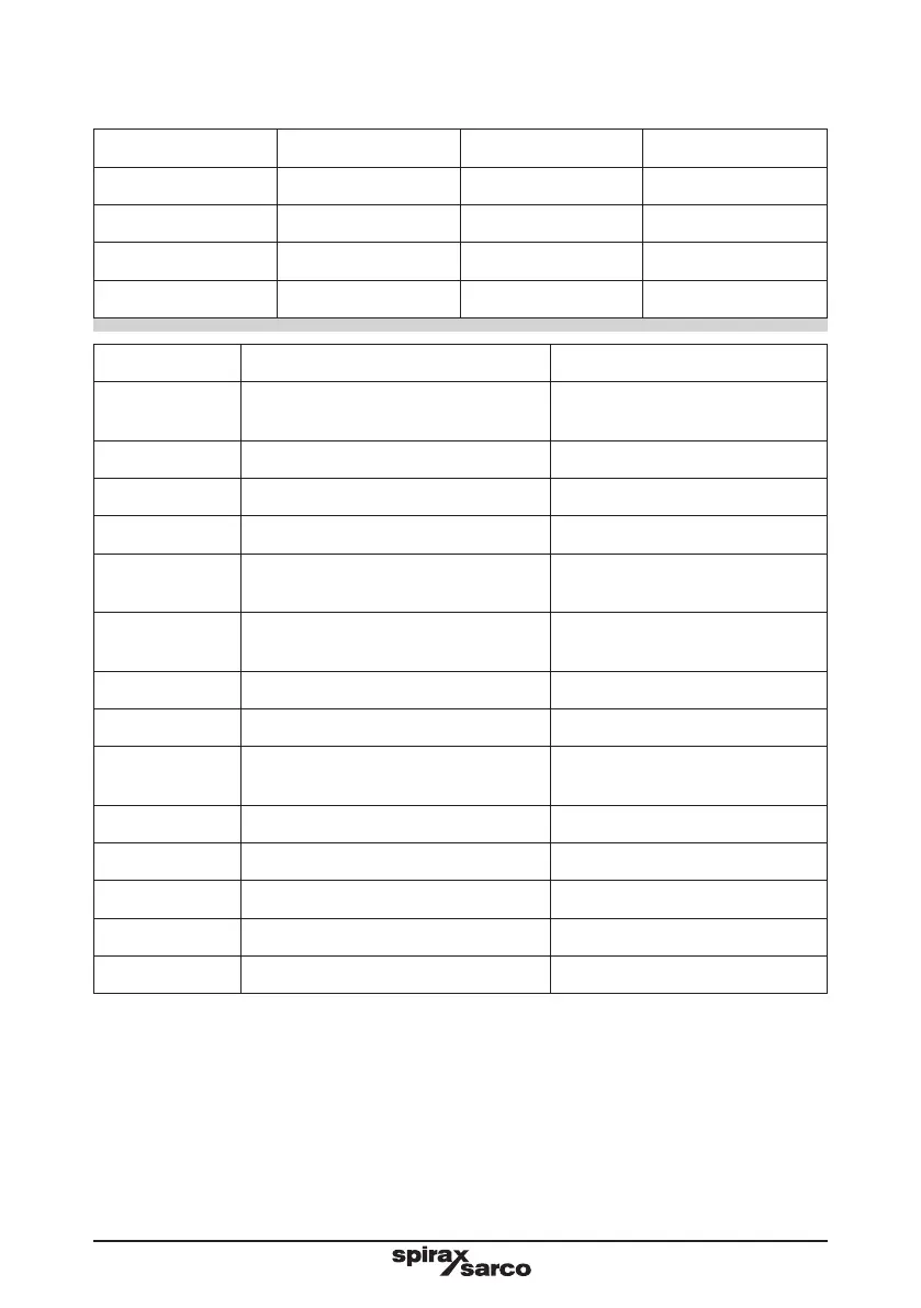
Bit 1 Bit 0 State Alarm code
0 0 Superheat 0x0000
0 1 Not applicable Not applicable
1 0 Saturated 0x0002
1 1 Sub-saturated 0x0003
Bit Set (1) Cleared (0)
Bit 2 (0x0004)
Pressure alarm is active
(too high or too low)
Pressure alarm is idle
Bit 3 (0x0008) Superheat margin active Superheat margin idle
Bit 4 (0x0010) Hi flow alarm is active Hi flow alarm is idle
Bit 5 (0x0020) Sensor constant alarm is active Sensor constant alarm is idle
Bit 6 (0x0040)
No signal from sensor alarm is
active
No signal from sensor alarm is
idle
Bit 7 (0x0080)
Power failed (has been turned off
and on) alarm is active
Power failed alarm is idle
Bit 8 (0x0100) Hi flow alarm has latched -
Bit 9 (0x0200) Sensor constant alarm has latched -
Bit 10 (0x0400)
No signal from sensor alarm is
latched
-
Bit 11 (0x0800) Power failed alarm has latched nothing
Bit 12 (0x1000) Low superheat (Low S-HT) alarm -
Bit 13 (0x2000) Over pressure alarm (OVEr PRES) -
Bit 14 (0x4000) - -
Bit 15 (0x8000) - -
A maximum of 12 Modbus registers can be polled together at the same frame. It has to be
noted that only a poll with a valid start address and quantity that falls within the supported
register range will produce a normal frame response. If you ask for a frame with start address
outside this range or a frame that the start address + quantity falls outside this range, the
TVA will reply with an 'illegal data address' error message. If the function code is incorrect,
it will reply with an 'illegal function' error message.
If a message is received with the wrong CRC, it will be ignored. The TVA response time is
not instant (look below) so wait for it to reply before asking for more data, otherwise it will
ignore new requests.

 Loading...


