8
Passeq Analog Code
®
Plug-in
Overview
Operation
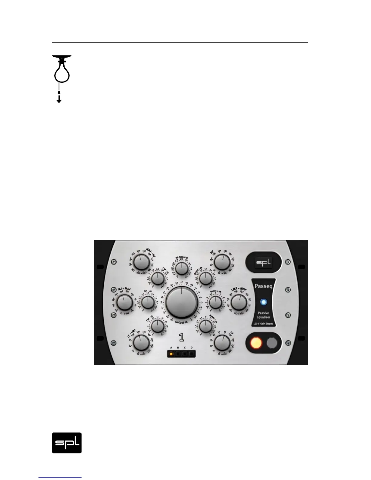
Layout of Operational Elements
Initially one might be struck by the circular arrangement of the
Passeq’s control elements. As unusual as this first appears, the
more understandable and clearer this layout becomes when one
looks closer.
Along with the fact that we simply like this design from an aestheti-
cal view, this layout makes even more sense with respect to the
idea of the passive EQ concept itself: In a passive design, filters for
boosting and cutting a frequency range are physically separated
from each other. Reflecting this fact, the elements left of the cen-
tral output control perform level cuts, while controls to the right of
this central regulator serve as signal boost controls. Cut and boost
switches are positioned next to the appropriate frequency band
selector and frequency bands are arranged from low to high from
the standpoint of both physical and frequency range layout—all
in all a clear overall functional picture though without much in the
way of boring routine.
Passeq Single – the space-saving single channel GUI