4
Important: Make sure that the drain hose is not kinked and that
water ow is not restricted.
3) Through the oor to a separate trap. The trap must be vented to
prevent siphoning. To provide proper venting, install an Air Gap Kit
(available at most hardware stores).
4) To the faucet using a Faucet Adapter Kit (available separately).
• Use a U-Clamp (provided in your accessories packet) or suitable item to
secure the outlet end of the drain hose (included in the plastic bag
provided inside of your washer-dryer).
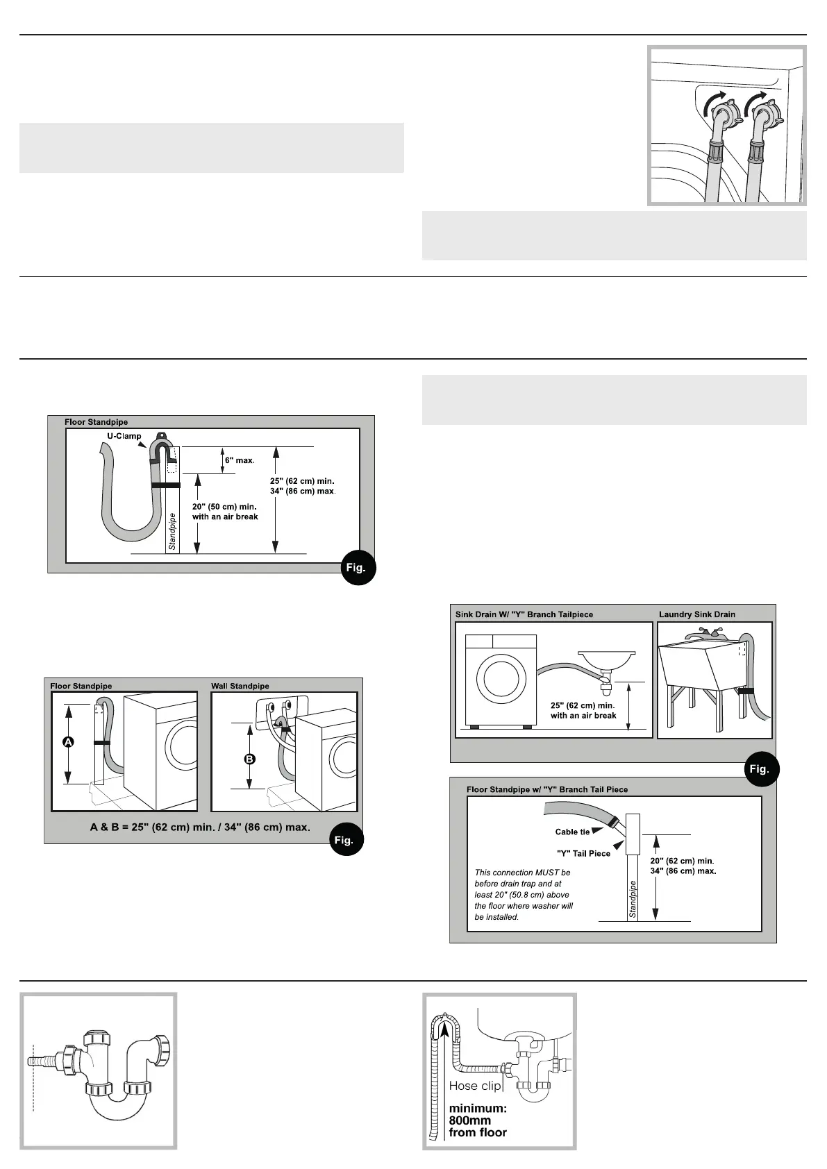
• Insert the outlet end of the drain hose into the standpipe, wall or oor
drain (Fig. 1).
NOTE: The outlet end of the drain hose MUST be at least 20” (50 cm)
above the base of the machine. No more than 6” of the drain hose should
be inserted into the drain pipe to prevent siphoning.
• Use a strap, cable tie, or similar item to hold the hose or the U-Clamp in place.
3
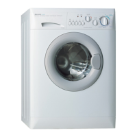
UNDER SINK METHOD
1. Cut the blocked end of the under sink
drainage unit.
2. Fix the hooked end support a minimum
of 24.4” (620 mm) from the oor.
3. Use a hose clip clamp to securely attach
the grey drainage hose end to the under
sink drainage unit using a hose clamp.
DRAINAGE
• Standpipe Diameter/Capacity - Needs a 1 ¼” minimum diameter
standpipe with a minimum carry-away capacity of 7 gallons per minute.
• Top of Standpipe - Must be between 25” - 34” high from the bottom of the machine.
• Outlet End of Drain Hose (provided with the unit) - Must be at least
20” above the bottom of the washer-dryer. An air break must be
available at the standpipe to avoid siphoning. No more than 6” of the
drain hose should be inserted into the drain pipe to prevent siphoning.
CONNECTING THE DRAIN HOSE
It is possible for the water to be discharged into a sink, standpipe or
drainpipe, but an air break must be available at a min. 20” height to
prevent the machine from siphoning (Fig. 1).
1
Standpipe Drain System - Installations require a minimum 1 ¼” (3.2 cm)
diameter standpipe with a minimum carry away capacity of 7 gallons (26
liters) per minute.
Wall or Floor Standpipe Drain System - The top of the standpipe must be
between 25” (62 cm) - 34” (86 cm) from the bottom of the washer-dryer (Fig. 2).
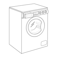
Sink Drainpipe System - Entry into the sink drain system must be above the trap
(Fig. 3). When routing the drain hose through cabinets or walls, use a protective
material such as electrical or duct tape to cover sharp edges that could damage the
drain hose. Use a suitable clamp to secure the drain hose to the “Y” branch or the
disposer. With a sink drainpipe system, you may connect directly:
1) to a disposer by following the manufacturers attachment method.
2) to a “Y” branch tail piece (available at most hardware stores).
CONNECTING WATER INLET
If the water pipes you will be connecting to are new or unused, run the
water until clear to remove any debris that could clog the water valve
screens or valves before connecting the machine.
NOTE: Supply shut-o valves should be easily accessible.
Important: Water pressure MUST range within the values indica-
ted on the “Technical Data” chart.
1. Screw the cold water ll hose (C blue
connector) onto the cold water supply
until tight.
2. Turn on the cold water supply and
check for leaks, tighten if necessary.
3. Screw the hot water ll hose (H red
connector) onto the hot water supply
until tight.
4. Turn on the hot water supply and
check for leaks, tighten if necessary.
Important: Do not use excessive force. Damage to the couplings
can result. The couplings should be tightened by hand; a tool should
only be used if a leak occurs.