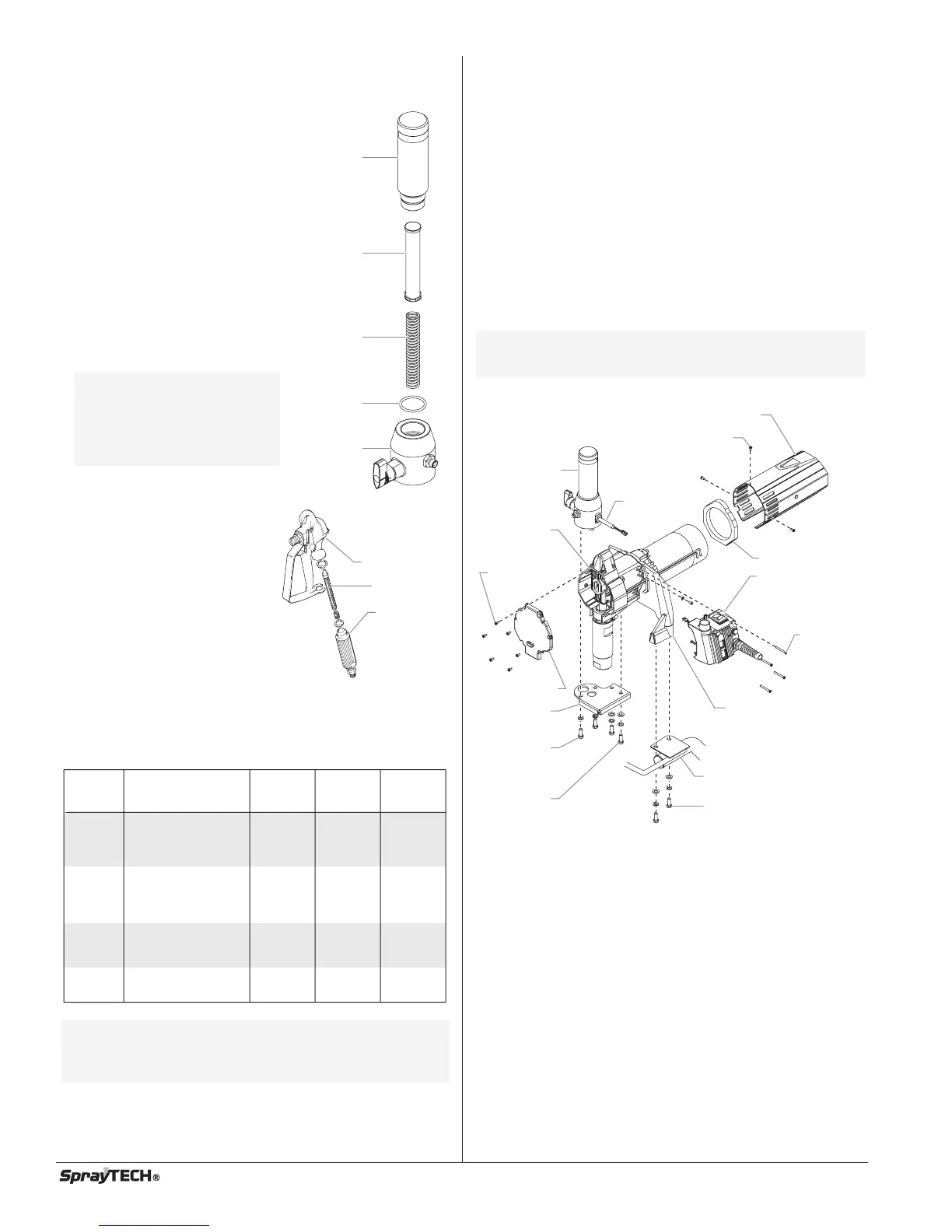
Replacing the Filters
Pump Filter
1. Loosen and remove the filter
body by hand.
2. Slip the filter off of the core
spring.
3. Inspect the filter. Based on
inspection, clean or replace the
filter.
4. Inspect the o-ring. Based on
inspection, clean or replace the
o-ring.
5. Slide the new or cleaned filter
over the core spring. Push the
filter into the center of the filter
housing.
6. Slide the filter body over the filter
and thread it into the filter
housing until secure.
Gun Filter
1. Pull the trigger guard forward
so that it comes loose from
the handle.
2. Unscrew the handle from the
housing and remove the old
filter.
3. Slide the new filter, taper end
first, into the gun housing.
4. Replace the handle, washer
and spring. Screw the handle
into the housing until hand-
tight. Replace the trigger
guard.
Choosing the Correct Spray Gun Filter
Use the proper gun filter based on the type of material being
applied as shown below.
NOTE: For more detail, part number information, and
assembly drawings at larger scale, please see
the G-10 2-Finger/4-Finger Airless Spray Gun
Owner's Manuals (P/N 0297076 or P/N 0508832).
Part no. Application Filter
type
Mesh
number
Color of
Filter
body
0089960 Synthetic resin,
enamels, clean
varnishes, stains
azures
Extrafine 0.084 mm red
0089959 Base coat enamels,
primer enamels,
fillers, marking paints,
textured enamels
Fine 0.140 mm yellow
0089958 Emulsions,
latex paints,
acrylic paints
Medium 0.315 mm white
0089957 Filler paints,
large area surfaces
Coarse 0.560 mm green
Gun Housing
Filter
Handle
NOTE: The filter body
should be hand-
tightened, but make
sure it is seated
fully into the filter
housing.
Filter
Body
Core
Spring
Filter
O-ring
Filter
Housing
8©SprayTECH. All rights reserved.
Replacing the Motor Assembly
1. Perform the Pressure Relief Procedure and unplug the
unit.
2. For Upright cart units, remove the return hose from the
clamp on the siphon tube. Unscrew the siphon tube from
the inlet valve housing.
3. For Low Boy cart units, remove the retaining ring from the
bottom of the inlet valve housing using a snap ring pliers.
Remove the suction set assembly.
4. Loosen and remove the high-pressure hose from the
nipple on the back of the fluid section and from the bottom
of the filter assembly.
5. Loosen and remove the six front cover screws. Remove
the front cover.
6. Loosen and remove the three motor shroud screws.
Remove the motor shroud.
7. Slide the baffle off of the end of the motor.
8. Loosen and remove the four pressure control assembly
screws. Carefully pull the pressure control assembly off of
the gear box housing.
9. At the pressure control assembly:
a. Disconnect the red wire and black wire coming from the
motor.
b. Disconnect the phone jack-style connector on the black
wire coming from the transducer.
10. Set aside the pressure control assembly.
11. Loosen and remove the two filter assembly screws. Lift
the filter assembly off of the filter bracket.
12. Loosen and remove the transducer from the filter housing.
Do not pull the transducer wire out of the gear box
housing.
13. Loosen and remove the two filter bracket screws.
Remove the filter bracket from the adapter plate.
14. Loosen and remove the four pump mounting screws. Lift
the pump off of the cart and place face down on a work
bench.
Motor Shroud
Filter
Assembly
Gear Box
Housing
Filter
Bracket
Filter
Assembly
Screw
Filter
Bracket
Screw
Front Cover
Motor Shroud Screw
Adapter Plate
Pump Mounting
Screw
Cart
Pressure
Control
Assembly
Pressure
Control
Assembly
Screw
Baffle
Front Cover
Screw
Transducer
NOTE: Before removing the baffle, note the location of
the baffle on the motor so it can be positioned in
the same spot during reassembly.