RD7000+ Operation Manual 5
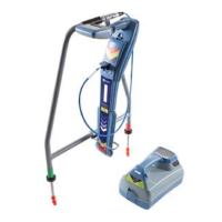
2.2 Tx-1, Tx-3 and Tx-10
transmitters
2.2.1 Transmitter features
Keypad.
LCD.
Removable accessory tray.
Rechargeable battery pack.
2.2.2 Transmitter keypad
Power key : Switches the unit on and off. Opens
the transmitter menu.
Frequency key : Selects frequency. Menu
navigation key.
Up and down arrows
: Adjusts the output
signal. Scrolls through the menu options.
Measure key : Toggles measurement display
between volts, current and impedance.
Note: displayed measurements are based on the
currently selected mode or the attached accessory,
if applicable. Opens a submenu.
2.2.3 Transmitter screen icons
Battery icon: Indicates the battery level.
Alphanumeric description of selected operation mode.
Standby icon: Appears when the transmitter is in
Standby Mode.
Output level: Displays transmitter output power.
Clamp icon: Indicates when a clamp or other plug is
connected.
DC icon: Appears when the transmitter is powered
from a DC source.
Induction indicator: Appears when the transmitter is
in Induction Mode.
A-Frame (Tx-3 and Tx-10 only): Indicates when the
transmitter is in Fault-Find Mode.
CD Mode indicator (Tx-10 only): Indicates that the
transmitter is in Current Direction Mode.
Voltage warning indicator: Indicates that the
transmitter is outputting potentially hazardous
voltage levels.
Volume icon: Displays the volume level.
Pairing icon (Tx-3B and Tx-10B only). For use with
RD8000 locators only.
Bluetooth
®
icon (Tx-3B and Tx-10B only). For use
with RD8000 locators only.
1.
2.
3.
4.
5.
6.
7.
8.
9.
10.
11.
12.
13.
14.
15.
16.
17.
18.
19.
20.
21.