RD7000+ Operation Manual 3
Section 2 – System overview
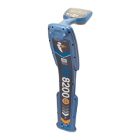
2.1 RD7000+ locator
2.1.1 Locator features
Keypad.
LCD with auto backlight.
Speaker.
Battery compartment.
Accessory slot.
Headphone jack.
2.1.2 Locator keypad
Power key : Switches the unit on and off.
Opens the locator menu.
Frequency key : Selects frequency.
Closes submenu.
Up and down arrows
: Adjusts the signal gain.
Scrolls through the menu options.
Antenna key : Toggles peak, null (PL and TL
models only) and combined peak/null modes.
Open submenu. Prolonged keypress toggles
between depth or current display on the LCD.
2.1.3 Locator screen icons
Indicates the signal strength and peak marker.
Signal strength: Numeric indication of signal strength.
Peak arrows: Indicates the location of the line relative
to the locator.
Battery icon: Indicates the battery level.
Volume icon: Displays the volume level.
Fault-Find arrows (PL and TL models only)
Radio Mode: Indicates when Radio Mode is active.
Power Mode: Indicates when Power Mode is active.
Accessory indicator: Indicates when an accessory is
connected.
A-Frame icon: Indicates when the A-Frame is
connected.
Operating mode indicator.
1.
2.
3.
4.
5.
6.
7.
8.
9.
10.
11.
12.
13.
14.
15.
16.
17.
18.
19.
20.
21.
Compass: Shows the direction of the located cable
relative to the locator.
Null / Peak icon: Indicates antenna selection.
Sonde icon: Indicates that the signal source is from
a sonde.
Line icon: Indicates that the signal source is from
a line.
Current / depth indicator.
22.
23.
24.
25.
26.