iv RD7000+ Operation Manual
6.2.1 Manhole covers 21
6.2.2 Using lighting columns 2
1
6.2.3 Finding a good ground point 2
1
6.3 Double-ended connections 2
2
6.3.1 Making a double-ended connection 2
2
Section 7 – Using Accessories 23
7.1 About accessories 23
7.2 Locator clamps 2
3
7.2.1 When to use clamps 2
3
7.2.2 Connecting a clamp 2
3
7.2.3 Available locator clamps 2
4
7.3 Transmitter clamps 2
4
7.3.1 Connecting the clamp 2
4
7.3.2 Available transmitter clamps 2
5
7.4 Sondes 2
5
7.4.1 When to use a sonde 2
5
7.4.2 Choosing a suitable sonde 2
5
7.4.3 Preparation 2
5
7.4.4 Propelling a sonde 2
5
7.4.5 Locating and tracing a sonde 2
6
7.4.6 Checking sonde depth 2
7
7.4.7 Types and range of sondes 2
7
7.5 Stethoscopes 2
8
7.5.1 When to use a stethoscope 2
8
7.5.2 How to use a stethoscope 2
8
7.5.3 Types of stethoscope 2
8
7.6 Submersible antenna 2
8
7.6.1 When to use a submersible antenna 2
8
7.6.2 How to use a submersible antenna 2
8
Section 8 – Fault-Finding 30
8.1 About fault-nding 30
8.2 Preparation 3
0
8.2.1 Connecting the transmitter 3
0
8.2.2 Reference readings 3
0
8.3 How to nd a fault 3
1
Section 9 – Extended Warranty, eCAL
™
and Maintenance 3
2
9.1 Product Registration and Extended Warranty 32
9.2 Centros
™
Manager 32
9.2.1 Installing Centros Manager 3
2
9.3 eCAL
™
32
9.3.1 Using eCAL
™
to validate the RD7000+ 33
9.3.2 Using eCAL
™
to retrieve the original
factory calibration certicate 33
9.4 Upgrading software 3
3
9.5 Care and maintenance 3
4
9.5.1 General 3
4
9.5.2 Batteries and power supply 3
4
9.5.3 Cleaning 3
4
9.5.4 Disassembly 3
4
9.5.5 Service and maintenance 3
4
Section 10 – Appendices 35
10.1 Specications for the locator and transmitter 35
10.2 Supported frequencies 3
5
10.3 Supported accessories 3
6
Table of figures
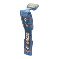
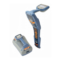
Figure 2.1: RD7000+ locator 2
Figure 2.2: locator keypad
2
Figure 2.3: locator LCD
2
Figure 2.4 RD7000+ transmitter
4
Figure 2.5: Rechargeable battery pack
4
Figure 2.6: transmitter keypad
4
Figure 2.7 transmitter LCD
4
Figure 4.1 Line tracing 1
3
Figure 4.2: Pinpointing a target line 1
3
Figure 4.3: Pinpointing with Peak/Null 1
3
Figure 4.4: Passive sweep 1
4
Figure 4.5: Inductive search 1
5
Figure 5.1: Taking a depth reading 1
6
Figure 5.2: Depth readings 1
6
Figure 5.3: Current readings 1
8
Figures 5.4 – 5.6: Taking current readings 1
8
Figure 5.7: Current readings using transmitter signals 1
9
Figures 6.1 – 6.4: Interference from services 2
0
Figure 6.5: Making double-ended connections 2
2
Figure 7.1: Connecting a locator clamp 2
3
Figure 7.2: Standard clamp 2
4
Figures 7.3 – 7.4: Connecting transmitter clamps 2
4
Figure 7.6: Sonde deployment 2
6
Figure 7.7: Locating a sonde 2
6
Figure 7.8: Calculating sonde depth 2
6
Figure 7.9: Standard sonde 2
7
Figure 7.10: Super small sondes 2
7
Figure 7.11: Sewer sonde 2
7
Figure 7.12: FlexiTrace 2
7
Figure 7.13: Using a submersible antenna 2
9
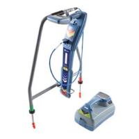
Figure 8.1: Cable sheath fault-nding 3
1
Figure 8.2: Locating cable sheath faults with
the locator and A-Frame 31