26
SRAM P5
MAINTENANCE
Technical Manual 2006
CABLE CHANGE
Dismantling shifter cable:
• Place shifter in gear position “1“.
• Do not remove the Clickbox from the axle
end.
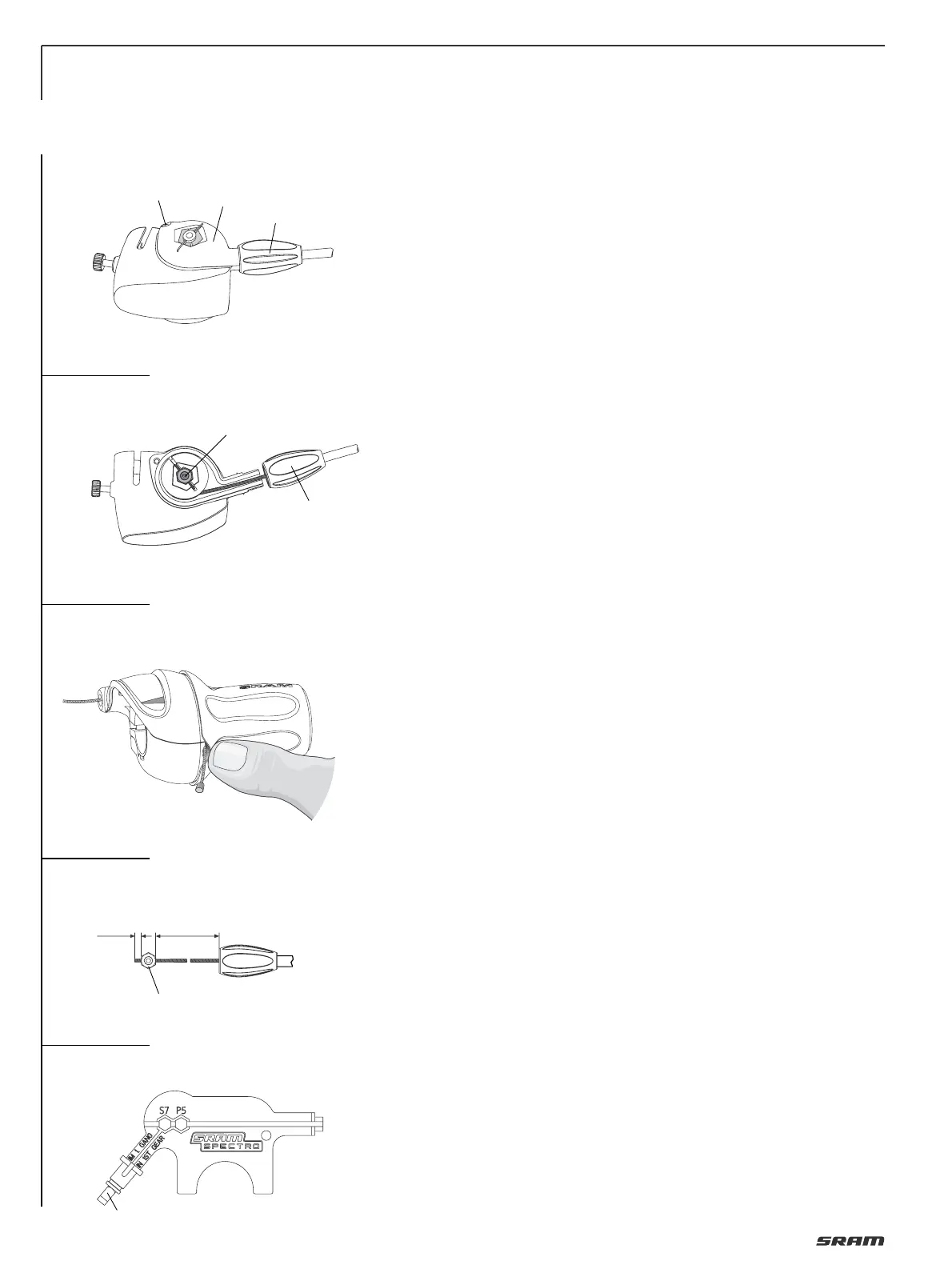
• Unscrew the adjusting screw (1, Fig. 5)
completely. Unscrew the cover screw (2),
brush aside the adjusting screw (1) and
remove the cover (3).
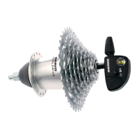
• Withdraw shifter cable and clamping
bolt (1, Fig. 6) upwards, loosen clamp
and pull clamping piece from the cable.
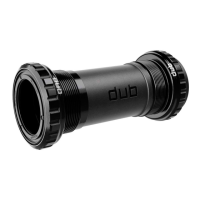
• Slightly lift the grip cover (Fig. 7), push
the cable out and discard.
Assembly shifter cable:
• Route new cable through shifter housing
and pull cable to seat cable head
completely into cable recess.
Feed the cable through the new cable
housing and adjusting screw.
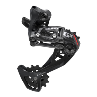
• Position clamping bolt (1, Fig. 8) at a
distance of 80 mm, tighten up with
1.5 Nm (13 in.lbs.) and cut off cable ends
to 2 – 3 mm. For positioning the clamping
bolt use adjust gauge (Fig. 9). (Part. No.
65 0324 107 000)
• Locate clamping bolt (1, Fig. 6) and place
shifter cable around the carrier cylinder
(counter-clockwise winding).
• Position the cover (3, Fig. 5) and tighten
up with the cover screw (2).
Torque 0.35 – 0.45 Nm (3.1 – 4.0 in.lbs.).
Screw in the adjusting screw (1)
completely.
Advice:
• If you want to remove the Clickbox from
the axle end for changing the cable, do
as follows:
– Place shifter in gear position “1“.
– Loosen the knurled screw and pull the
Clickbox off the axle.
– Now it’s essential to push the end (1,
Fig. 8) of the adjust gauge completely
into the Clickbox and tighten up the
knurled bolt (so that you maintain the
initial tension of the spring inside the
Clickbox).
– Change cable as per description above.
• If you remove the Clickbox from the
axle and change the cable without
using the end of the adjust gauge, then
you will lose the initial tension of the
spring inside the Clickbox. In this case
you must assemble the cable by placing
it around the carrier cylinder with an
additional winding (Fig. 6).
7
5
6
8
9
2
1
1
2
+1
mm
80
±0,5
mm
2
3
1
1