41
SRAM T3
MAINTENANCE
Technical Manual 2006
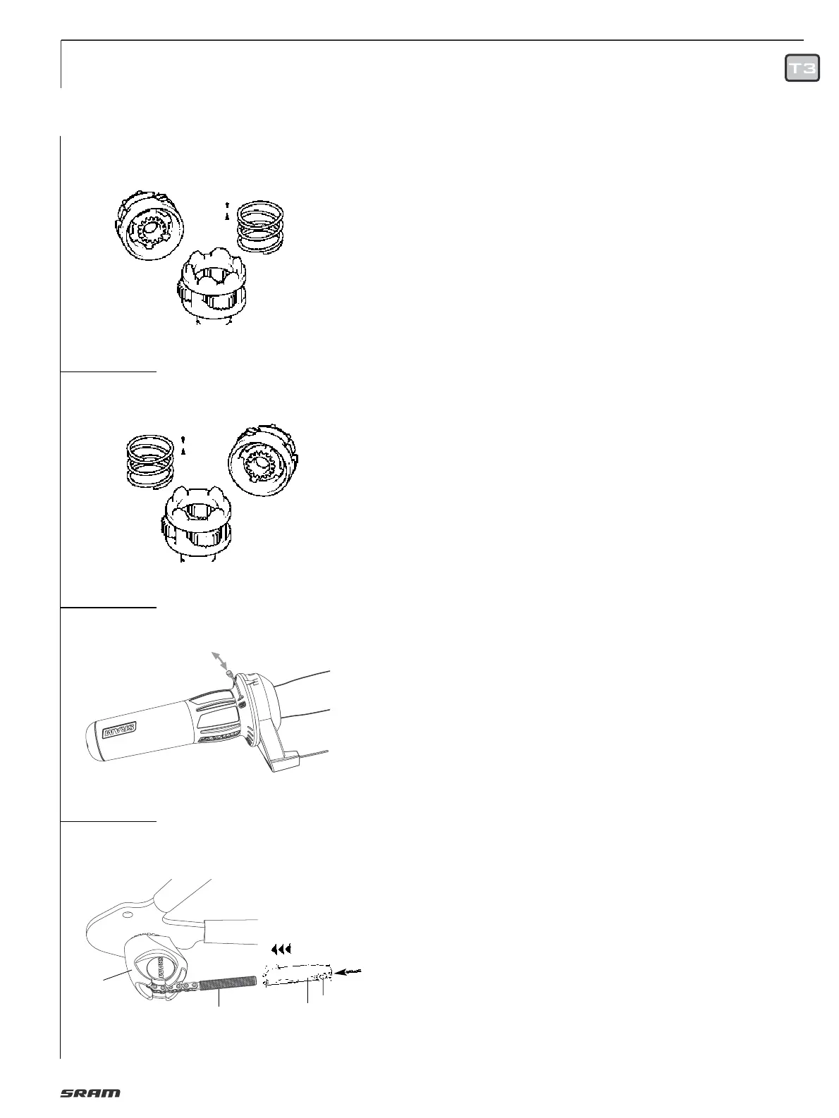
REASSEMBLY HUB
see Fig. 1 / 2 / 3
Lubrication see “
MAINTENANCE/
LUBRICATION
“.
• Clamp the hub axle (10) with the slot for
thrust block upwards), fit ring gear (11)
and align the large bore in the coupling
wheel with the slot. Position the radius
of the sliding key (12) facing downwards
and turn the coupling wheel slightly.
• Fit the compression springs (13 and 14).
• Place ball retainer with balls in (16) on
ring gear (11), mount driver (17), fit fixed
cone and lock with hexagonal nut (22),
tightening torque 15 – 20 Nm
(133 – 177 in.lbs).
• Turn hub over and slide on planet carrier
(9) – thrust washer (X) must first be fitted
for types MH 3105/3125. (For type MH
3115, this washer is already integrated in
the planet carrier). Mount thrust washer
(8) and place safety washer (7) in the
recess of the axle.
• Screw brake cone (6, type MH 3111) onto
the flat thread – for types MH 3105/3125
mount pawl carrier (b) and secure in
place using safety washer (c).
• Fit hub shell (5) – turning it counter-
clockwise slightly to get past the stop
notches – until the shell runs cleanly
onto the ball retainer.
• For type MH 3115, insert the brake slee-
ve (4) so that the spring end of the fric-
tion spring on the brake cone (6) sits in
one of the two slots on the brake sleeve.
Insert the ball retainer and fit the lever
cone – move the lever cone lightly until
the lugs on the brake lever catch in the
grooves on the adjusting cone.
• Adjust the hub clearance by screwing on
hexagonal nut (1) until the hub shell runs
free of play but not under tension. Lock
with a second nut to a tightening torque
of 15 – 20 Nm (133 – 177 in.lbs.).
• For type MH 3105 insert ball retainer (3),
mount adjusting cone (d) with dust cap
(e) and hexagonal nuts (1). Adjust the
hub clearance as for type MH 3115.
• For type MH 3125, the ball retainer (f)
and dust cap (pressed in) normally
remain in the hub shell. The hub
clearance is set with adjusting cone (D)
as for type MH 3115.
CABLE CHANGE
Dismantling shifter cable:
• Use only new cable and compression-
less cable housing
• Detach the cable from the internal hub.
• Remove the cable housing. Cut the cable
off 15 cm (6") from the shifter barrel
adjuster. Discard the old cable and cable
housing.
• Line up the ‘3’ gear number mark with
the indicator mark.
• Remove and discard the rest of the old
cable (Fig. 6).
Assembly shifter cable:
• Feed the new cable through the shifter.
• Feed the cable through the new cable
housing and stops.
• Feed the shifter cable into the locating
sleeve (5, Fig. 7), fix at the appropriate
length using the clamping bolt (1). Allan
key 2.5 mm, tightening torque 1.5 Nm
(13 in.lbs.). Shorten any cable which is
sticking out.
• Connect to the hub: push locating sleeve
(2, Fig. 7) loosely onto small pull rod (3).
ADJUSTMENT
• Place the shifter in gear position "3".
Move the crank to check that the gear
is engaged.
• To make the adjustment, the cable must
be taut in third gear to be able to transfer
a shift movement directly to the hub.
• Push locating sleeve (2, Fig. 7) onto the
small pull rod (3) until the control cable
is taut. Make sure that you don’t pull the
indicator chain out of the deflection
pulley (4).
Check:
• Place shifter in gear position "1" while
moving the crank.
• Setting too loose: In gear position "1" the
tension chain can be pulled out of the
deflection pulley by hand.
• Setting too tight: It is difficult to place
the shift lever in gear position "1".
• If required, readjust the shift mechanism
(in third gear).
Ø 1,1 mm
Ø 1,4 mm
6
4
5
7
2
1
3
4
5
 Loading...