
L
Lisa CruzAug 14, 2025
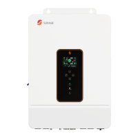
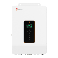
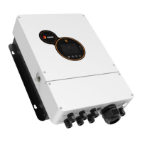
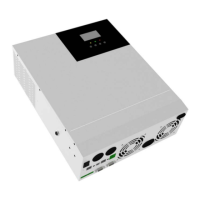
How to fix Srne ASF4880U180-H Inverter screen when it shows no display?
- HHenry JimenezAug 14, 2025
If your Srne Inverter screen isn't displaying anything, first ensure the circuit breaker is closed and the rocker switch is turned ON. If it's in sleep mode, push any button on the panel to wake it up. This should resolve the issue.