Hardware UM0289
6/29
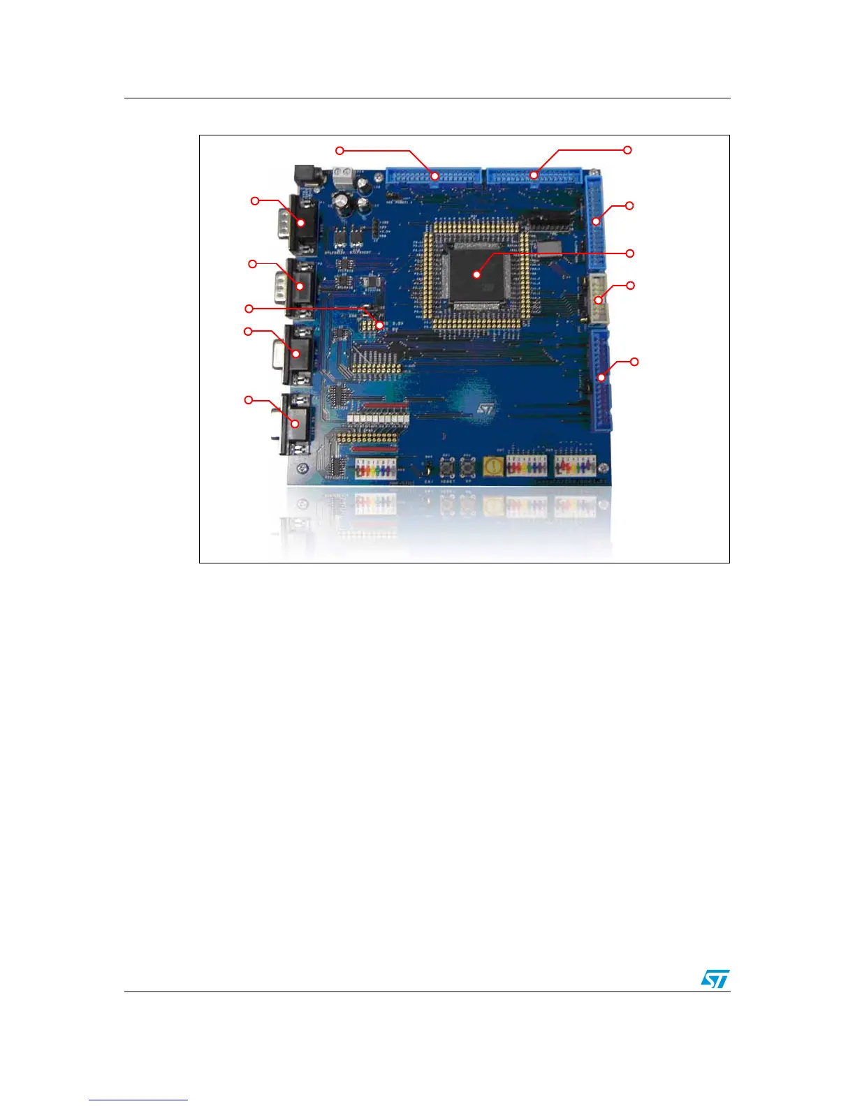
Figure 3. MDK-ST10 board
Note: Refer also to Section 5.1.2: Board configuration on page 23
The default configuration of the board (once programmed) is:
● EA jumper: 1 (in order to obtain the fetch of the code from internal flash of
microcontroller)
● SW3 switches: all OFF
●
SW5 switches:
– Switch 2 (CSEL 0): ON
– Switch 7 (CLK 1): ON
– Other switches: OFF
● Selector J206: "PRACTI" position (in order to connect micro lines to powerSPIN
connectors)
These configurations impose a 60 MHz core clock frequency and leave port 6 of
microcontroller free for I/0s (needed because P6.0=CS0 is used to manage powerSPIN
boards)
To better understand how powerSPIN boards are managed by control board, Ta bl e 1
provides a description of the powerSPIN connectors:
MC_CONNECTOR
POWERSPIN_2
ST10F276
VN808 / GP
POWERSPIN_3
RS232
RS485
I
2
C
CAN2
CAN1
POWERSPIN_1