UM0289 Hardware
9/29
2.3 Feedback board
In order to interface the control system with encoder signals coming from motors, a special
board, with two 20 pins connectors in the top side, is used (Feedback board).
This is a stackable board and has to be inserted using the four 36-pin connectors around the
microcontroller in the MDK-ST10 board. The insertion orientation is indicated with a dot in a
corner of the board (corresponding to pin 1 of the ST10 MCU)
The two connectors (Conn1 J3, Conn2 J4), used to allow the encoder feedback, are
shielded with the pair of pins connected to GND.
The dimensions of this board are about 6.5 x 6.5 cm. The following tables show the pin
assignments for each connector.
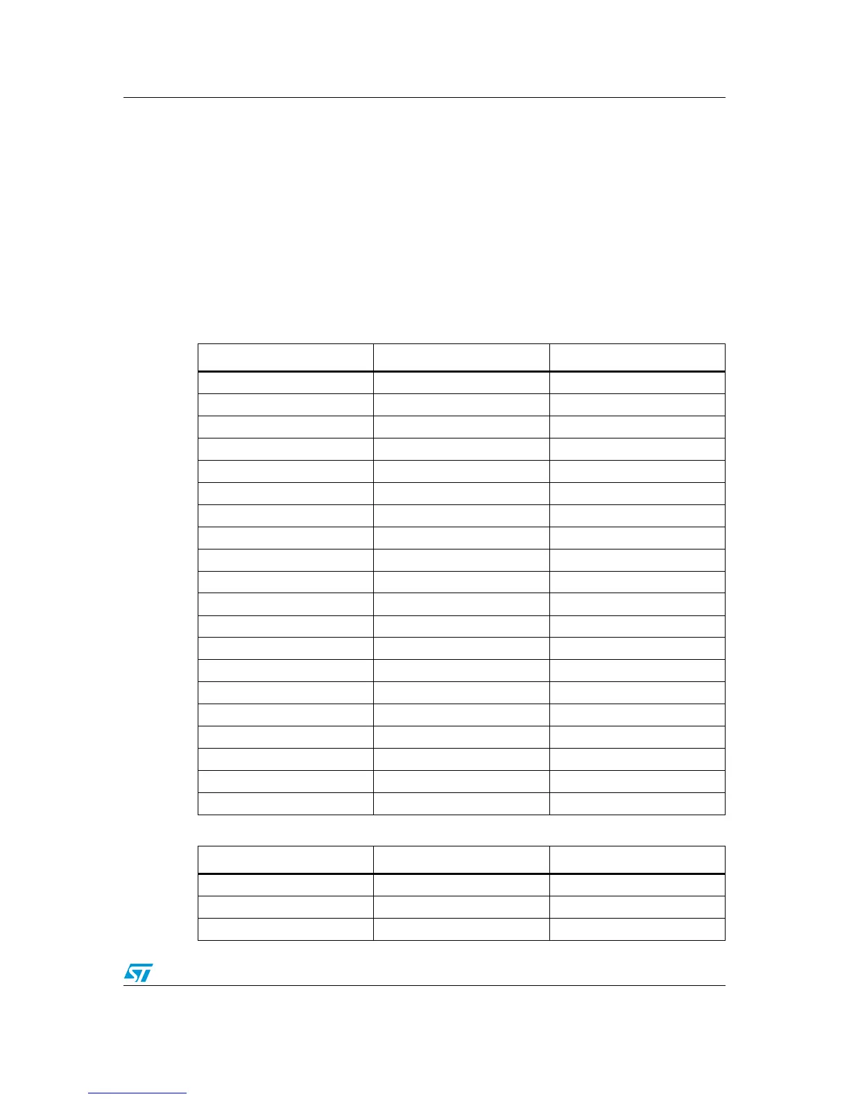
Table 2. Conn1 Feedback board
Table 3. Conn2 Feedback board
Conn.1 MDK-ST10 Pin Functionality
1 P3.7 T2IN (encoder_1 A)
2GND-
3 P5.15 T2EUD (encoder_1 B)
4GND-
5 P3.6 T3IN (encoder_2 A)
6GND-
7 P3.4 T3EUD (encoder_2 B)
8GND-
9 P3.5 T4IN (encoder_3 A)
10 GND -
11 P5.14 T4EUD (encoder_3 B)
12 GND -
13 P2.6 CC16 (capture / GPIO)
14 GND -
15 P1L.3 GPIO / ADC In
16 GND -
17 P1L.4 GPIO / ADC In
18 GND -
19 +5V -
20 GND -
Conn.2 MDK-ST10 Pin Functionality
1 P1L.5 GPIO/ ADC In
2GND-
3 P2.7 CC7 (capture / GPIO)