UM0289 ST10 firmware
21/29
4.2 Control algorithm
Communication layer after the reception and checking of a complete frame puts the
microcontroller in an execution state in which the right control layer function is involved.
The management of open loop signals is executed with functions that directly act in the
register of PWM signals or through the pins for the right generation of connector signals.
Closed loop operations, are instead managed through three independent ISR where the
reload timing depends on the closed loop time of the specific control.
The speed reference is expressed in terms of encoder pulses, counted in the closed loop
timing imposed, so each ISR works with the actual values of encoder inputs and with PWM
duty cycles to perform a PID action for reach the right value of encoder reference.
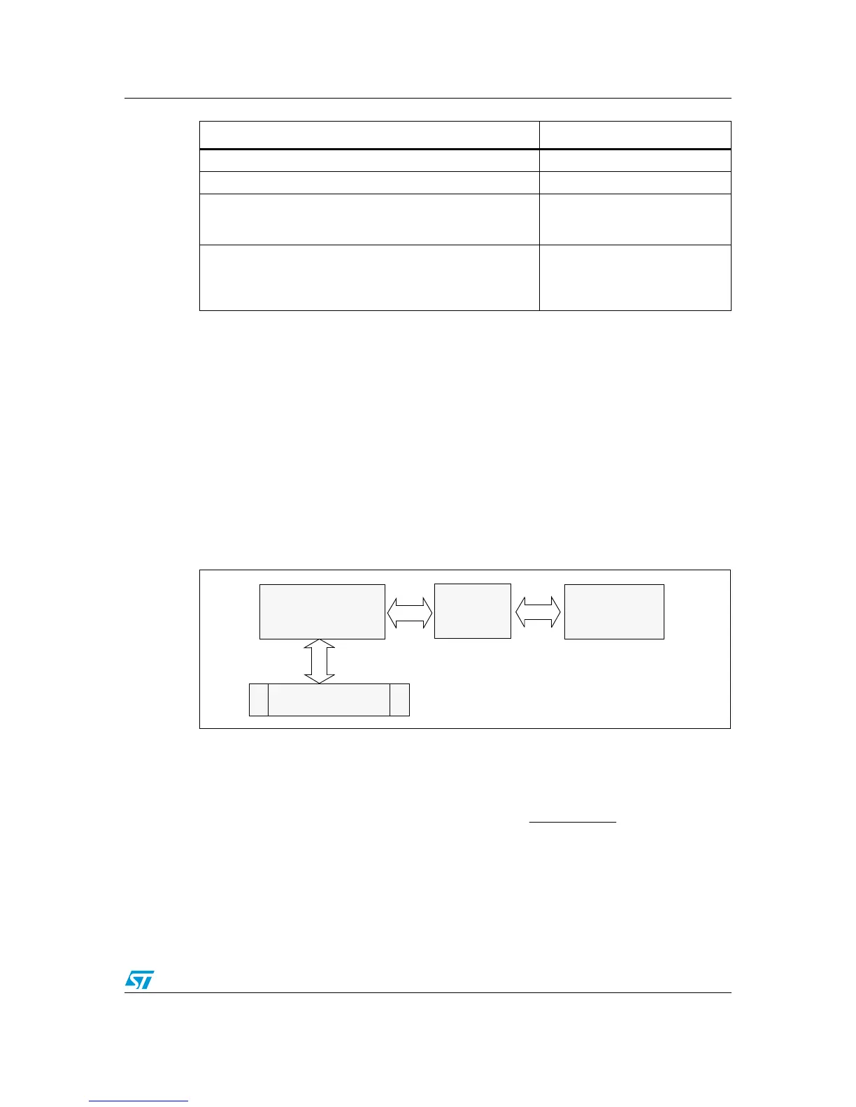
Figure 12. Algorithm block diagram
Figure 12 shows how the two modules interact (through shared memory) to perform
eMotion operations.
The PID algorithm implemented is approximated with the following formula:
Set PWM% to 22% for 6235 driver on connector 2 08-02-2A-16-4A
Set 2ms of control loop time for a 6205 driver on connector 2 0A-02-2B-05-3C
Set control for a DC motor with a 1024/revolution encoder,
connected to the first connector. Set the speed reference to 100
rpm with control parameters of P=0.04,I=0.02,D=0.01
09-0C-1B-CD-04-00-00-64-00-04-
00-02-00-01-6D
Receive the parameters of connector 3 with a BLDC motor with
500/revolution encoder controlled at 200 rpm with P=0.60,
I=0.02,D=0.00 and control loop of 1.2 ms. With actual PWM
signal 10% / 22 Khz
40-0F-3A-01-F4-00-0A-16-02-01-
00-C8-00-3C-00-02-00-00-A9
Frame Description Value (Hex)
Communication
Layer
Shared
memory
Control
Layer
SERIAL BUFFER
T
nene
DTkeInePnu
n
K
)1()(
)()()(
1
−−
⋅+⋅⋅⋅+⋅=
∑
=
 Loading...


