EasyManua.ls Logo

ST NUCLEO-H7A3ZI-Q User Manual

ST NUCLEO-H7A3ZI-Q
51 pages
To Next Page IconTo Next Page
Page #1 background imageLoading...
Page #1 background image
December 2019 UM2408 Rev 2 1/51
1
UM2408
User manual
STM32H7 Nucleo-144 boards (MB1363)
Introduction
The STM32H7 Nucleo-144 boards based on the MB1363 reference board (NUCLEO-
H745ZI-Q, NUCLEO-H755ZI-Q, NUCLEO-H7A3ZI-Q) provide an affordable and flexible
way for users to try out new concepts and build prototypes, by choosing from the various
combinations of performance and power consumption features provided by the STM32H7
microcontroller. The ST Zio connector, which extends the ARDUINO
®
Uno V3 connectivity,
and the ST morpho headers provide an easy means of expanding the functionality of the
Nucleo open development platform with a wide choice of specialized shields. The STM32H7
Nucleo-144 boards do not require any separate probe as they integrate the STLINK-V3E
debugger/programmer. The STM32H7 Nucleo-144 boards come with the comprehensive
free software libraries and examples available with the STM32Cube MCU Package.
Pictures are not contractual.
Figure 1. Nucleo-144 board (Top view) Figure 2. Nucleo-144 board (Bottom view)
www.st.com
Downloaded from Arrow.com.

Table of Contents

Question and Answer IconNeed help?

Do you have a question about the ST NUCLEO-H7A3ZI-Q and is the answer not in the manual?

ST NUCLEO-H7A3ZI-Q Specifications

General IconGeneral
MicrocontrollerSTM32H7A3ZIT6
CoreARM Cortex-M7
Operating Frequency280 MHz
Flash Memory2 MB
I/O PinsUp to 140
Architecture32-bit
Clock Frequency280 MHz
On-board DebuggerST-LINK/V2-1
Extension HeadersArduino Uno V3, ST morpho
GPIOUp to 140
CANYes
USBUSB 2.0 OTG
DAC2 x 12-bit DAC
ConnectivityUSB, CAN, UART, SPI, I2C
Voltage Supply3.3 V
Operating Temperature-40°C to +85°C
Debug InterfaceSWD
SRAM1 MB
RAM1 MB

Summary

Quick Start Guide

Getting Started

Step-by-step guide to configure and launch the demo application.

Hardware Layout and Configuration

Nucleo-144 Board Layout Overview

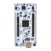
Overview of the board's main components and connectors.

Programming and Debugging the STM32H7 Target

Methods to program and debug the onboard STM32H7 MCU.

Power Supply and Power Selection

Details on various power supply inputs and configurations.

USART Communication

Details on USART3 interface connection options.

USB OTG FS or Device Functionality

Features and configuration for USB OTG/device communication.

Ethernet Interface

Ethernet functionality and pin configuration for specific board variants.

Solder Bridges Configuration

Detailed explanation of solder bridge functions and configurations.

Related product manuals