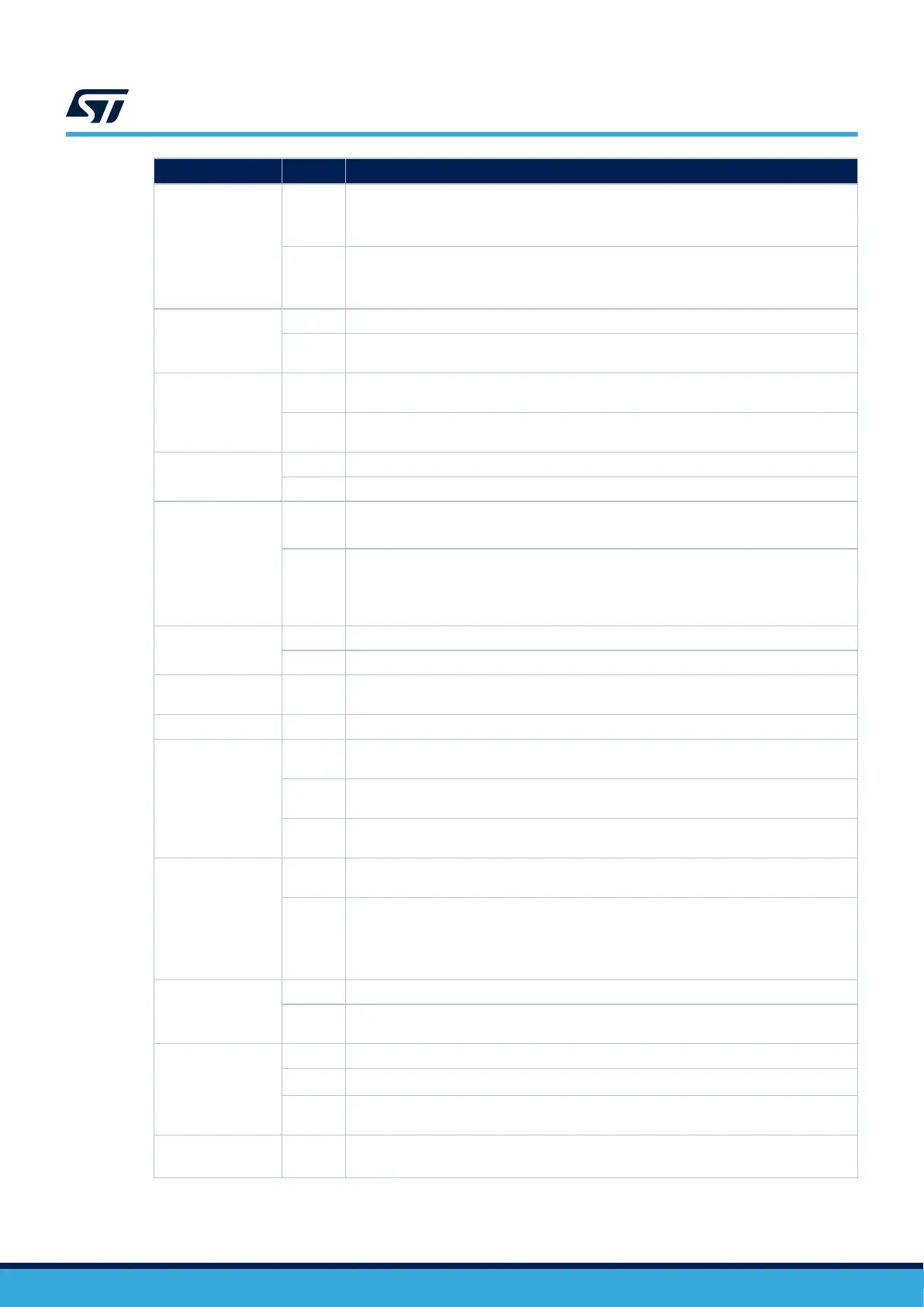
Solder Bridge
State
(1)
Description
SB18, SB24,
SB23, SB65
(USART3)
ON, ON,
OFF,
OFF
USART3 is connected to the Virtual COM Port (VCP) (default).
OFF,
OFF,
ON, ON
USART3 is connected to ARDUINO
®
D0 and D1.
SB19 (SDMMC_D0)
SB20 (SDMMC_D1)
ON SDMMC data (D0/D1) signals are connected to the ST morpho connector (CN12).
OFF
SDMMC data signals (D0/D1) are not connected to the ST morpho connector (CN12) to
avoid stubs on SDMMC data signals.
SB21 (PA11)
SB22 (PA12)
ON, ON
These pins can be used as GPIOs on the ST morpho connector (CN12). (SB27 and SB28
must be OFF).
OFF,
OFF
These pins are used as D- and D+ on the USB connector (CN13). (SB27 and SB28 must
be ON). (Default).
SB26
(VDD33_USB_2)
ON VDD33_USB_2 pin of STM32H5 is connected to 3V3.
OFF VDD33_USB_2 pin of STM32H5 is not connected.
SB29 (PB13)
SB30 (PB14)
ON, ON
PB13 and PB14 are used as the UCPD_CC1 and UCPD_CC2 signals.
(SB12 must be OFF)
OFF,
OFF
PB13 and PB14 can be used as GPIOs on the ST morpho connector (CN12). (SB12 must
be OFF).
PB13 can be used as the I2S_2_CK signal on the ST Zio connector (CN7) (SB12 must be
ON).
SB31 (PA9)
ON PA9 is connected and used as the UCPD_DBn signal (dead battery detection).
OFF PA9 can be used as GPIO on the ST morpho connector (CN12).
SB32
(VDD_MMC_1)
ON VDD_MMC_1 pin of STM32H5 is connected to VDD_MCU.
OFF VDD_MMC_1 pin of STM32H5 is not connected.
SB33, SB39 (PB3)
OFF, ON
SWO signal of the STM32H5 (PB3) is connected to the ST-LINK SWO input (SB33 must be
OFF).
ON, OFF
PB3 is connected on ST Zio connector (CN7) and can be used as I2S_3_CK/ SPI1_SCK
signals.
OFF,
OFF
PB3 can be used as GPIOs on the ST morpho connector (CN12).
RMII signals
SB34 (PG11), SB36
(PC5), SB37 (PG13),
SB38 (PA7), SB42
(PC4), SB58 (PA1),
SB62 (PC1), SB69
(PA2), JP6 (PB15)
ON
These pins are used as RMII signals and connected to Ethernet PHY. SB10 must be OFF.
PB15 can be used as I2S_2_SD on ST Zio (pin 3 of CN7) if not used on the ST morpho.
OFF
These pins can be used as GPIOs on the ST morpho connectors. PB15 can be used as
I2S_2_SD on ST Zio (pin 3 of CN7) if not used on the ST morpho.
SB35, SB67 (PE9)
ON, OFF PE9 is used as TIM1_CH1 on the ST Zio connector (CN9)
OFF, ON
PE9 is used as GPIO on the ST Zio connector (CN9) and the ST morpho connector
(CN12).
SB43, SB51
(LD1 green LED)
ON, OFF The green user LED (LD1) is connected to PB0. (default).
OFF, ON
The green user LED (LD1) is connected to D13 of the ARDUINO
®
signal (PA5).
OFF,
OFF
The green user LED (LD1) is not connected.
SB44, SB45
(32.768 kHz crystal)
ON, ON
PC14 and PC15 are connected to the ST morpho connector (CN11). R34 and R35 must be
OFF.
UM3115
Solder bridges and jumpers
UM3115 - Rev 2
page 25/44