Hardware layout and configuration UM2407
18/50 UM2407 Rev 2
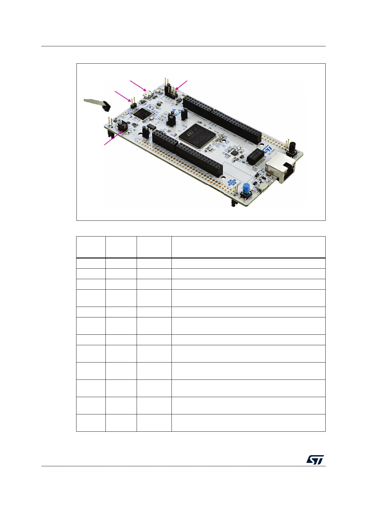
Figure 9. Connecting an external debug tool to program the on-board STM32H7
Table 5. MIPI-10 debug connector (CN5)
MIPI-10
Pin
STDC14
Pin
CN5 Designation
-1NCReserved
-2NCReserved
13 T_VCCTarget VCC
24 T_SWDIO
Target SWDIO using SWD protocol or Target JTMS
(T_JTMS) using JTAG protocol
35 GNDGround
46 T_SWCLK
Target SWCLK using SWD protocol or Target JCLK (T_JCLK)
using JTAG protocol
57 GNDGround
68 T_SWO
Target SWO using SWD protocol or Target JTDO (T_JTMS)
using JTAG protocol
7 9 T_JRCLK
Not used by SWD protocol, Target JRCLK (T_JRCLK) using
JTAG protocol, only for specific use
8 10 T_JTDI
Not used by SWD protocol, Target JTDI (T_JTDI) using JTAG
protocol, only for external tools
9 11 GNDDetect
GND detect for plug indicator, used on SWD and JTAG
neither
10 12 T_NRST
Target NRST using SWD protocol or Target JTMS (T_JTMS)
using JTAG protocol
MSv61202V2
Power supply selection
STLINK-V3E USB connector
JP1 STLK_RST
External debug tool

 Loading...


