Hardware layout and configuration UM2407
22/50 UM2407 Rev 2
Figure 12. Power supply input from 5V_EXT (5 V, 500 mA max)
6.4.4 External power supply input from USB CHARGER (5 V)
When STM32H7 Nucleo-144 board is power supplied by a USB charger on CN1 (Refer to
Tabl e
8 and Table 13), the jumper configuration must be the following: Jumper JP2 on
pin 7-8 ‘CHGR’.
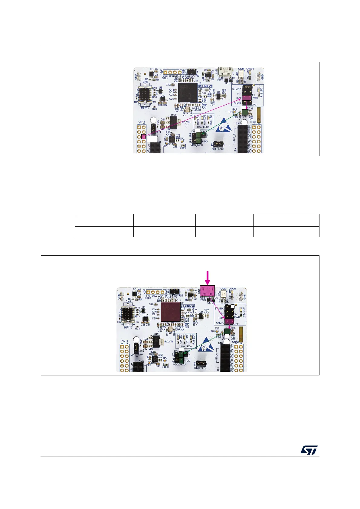
Figure 13. Power supply input from STLINK-V3E USB connector with a USB charger (5 V)
6.4.5 External power supply input from 3V3_EXT (3.3 V)
When the 3.3 V is provided by a shield board, it is interesting to use the 3V3 (CN8 pin 7 or
CN11 pin 16) directly as power input (Refer to
Table 9 and Figure 14). In this case,
programming and debugging features are not available, since the STLINK-V3E is not
powered.
Table 8. External power sources: CHGR (5 V)
Input power name Connector pins Voltage range Max current
CHGR CN1 5 V -
MSv61206V2
NO DEBUG
CN1
5V
3V3
USB CHARGER
3V3

 Loading...


