Hardware layout and configuration UM2407
20/50 UM2407 Rev 2
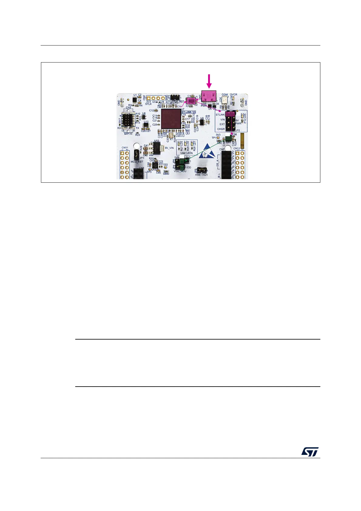
Figure 10. Power supply input from STLINK-V3E USB connector with PC (5 V, 500 mA max)
If the USB enumeration succeeds, the 5V_ST_LINK power is enabled, by asserting the
PWR_ENn signal from STM32F723IEK6 ‘STLINK-V3E’ (U7). This pin is connected to a
power switch STMPS2151STR (U2), which powers the board. The power switch
STMPS2151STR (U2) features also a current limitation to protect the PC in case of short-
circuit onboard. If an overcurrent (more than 500
mA) happens onboard, the red LED LD6 is
lit.
Nucleo board and its shield on it can be powered from STLINK-V3E USB connector CN1,
but only the STLINK-V3E circuit gets power before USB enumeration because the host PC
only provides 100
mA to the board at that time.
During the USB enumeration, the Nucleo board asks for the 500 mA power to the host PC.
• If the host is able to provide the required power, the enumeration finishes by a
SetConfiguration command and then, the power switch STMPS2151STR is switched
ON, the Green LED LD5 is turned ON, thus Nucleo board and its shield on it can
consume 500 mA current, but no more.
• If the host is not able to provide the requested current, the enumeration fails.
Therefore, the STMPS2151STR power switch (U2) remains OFF and the MCU part
including the extension board is not powered. As a consequence, the GREEN LED
LD5 remains turned OFF. In this case, it is mandatory to use an external power supply.
Warning: In case the maximum current consumption of the
STM32H7 Nucleo-144 board and its shield boards exceed
300 mA, it is mandatory to power the STM32H7 Nucleo-144
board, using an external power supply connected to E5V, V
IN
or +3.3 V.
6.4.2 External power supply input from VIN (7 V to 12 V, 800 mA max)
When STM32H7 Nucleo-144 board is power supplied by VIN (Refer to Table 6 and
Figure 11), the jumper configuration must be the following: Jumper JP2 on pin 3-4 ‘VIN’
MSv61203V2
U7
STM32F723
STLINK-V3
CN1
U2
5V
3V3
PC
3V3

 Loading...


