EasyManua.ls Logo

STA-RITE 700E Series - User Manual

STA-RITE 700E Series
8 pages
Print Icon
To Next Page IconTo Next Page
Loading...
Carefully read and follow all safety instructions in this
manual or on pump.
This is the safety alert symbol. When you see this
symbol on your pump or in this manual, look for one of the
following signal words and be alert to the potential for
personal injury.
warns about hazards that will cause serious
personal injury, death or major property damage if ignored.
warns about hazards that can cause serious
personal injury, death or major property damage if ignored.
warns about hazards that will or can cause
minor personal injury or property damage if ignored.
The word NOTICE indicates special instructions which are
important but not related to hazards.
NOTICE: Pump must be installed in a vertical position only.
Installing pump in any other position will void warranty.
1. To avoid serious injury and/or property damage, read
these rules and instructions carefully.
2. Check your local codes before installing. You must
comply with their rules.
3. Vent sewage or septic tank according to local codes.
4. Do not install pump in any location classified as
hazardous by National Electrical Code, ANSI/NFPA
70-1984.
5. Pump normally runs hot. To avoid burns when servicing
pump, allow it to cool for 20 minutes after shut-down
before handling it.
6. Do not run pump dry. Dry running can overheat pump
and will void warranty.
7. Pump is permanently lubricated. No oiling or greasing is
required in normal operation. For overhaul, see
instructions under "Service".
Hazardous voltage. Can shock, burn, or
cause death. During operation the pump is in water. To
avoid fatal shocks, proceed as follows if pump needs
servicing:
8A. Ground pump according to all applicable codes and ordi-
nances.
8B. Disconnect power to outlet box or circuit breakers before
servicing.
8C. To reduce risk of electric shock, take care when changing
fuses or resetting circuit breakers. Do not stand in water
when working on control box or with circuit breakers.
Single Phase Pumps:
8D. When using cord and plug, plug into a grounded outlet with
it’s own individual branch circuit. When wiring to a system
control, connect pump ground lead to system ground.
Three Phase Pumps:
Risk of electrical shock. Do not remove cord
or strain relief. Do not connect conduit to pump.
8E. Three phase pumps are intended for permanent
connection only. Provide strain relief at control box for
power supply cord connection to box. All control compo-
nents must be UL listed and suitable for end use
application. Only qualified personnel should install and
service the pump and associated control equipment.
INSTALLATION
Risk of electrical shock. Can burn or kill.
Do not lift pump by power cord. See “Cord Lift Warning” on
Page 3.
NOTICE: Install pump on a hard, level surface (cement,
asphalt, etc.). Never place pump directly on earth, clay or
gravel surfaces. Basin must be at least 18" (458 mm) in
diameter and 30" (762 mm) deep.
OWNER'S MANUAL
Installation • Operation • Repair Parts
Submersible, Effluent & Sewage/Solids Handling Pumps
700E/700EH, 700S and 900S Series,
60 Hz, Single and Three Phase
Printed in U.S.A. © 2002 S325 (Rev. 4/2/02)
SAFETY INSTRUCTIONS
Question and Answer IconNeed help?

Do you have a question about the STA-RITE 700E Series and is the answer not in the manual?

Summary

Safety Instructions

Safety Alert Symbol and Signal Words

Explains the safety alert symbol and signal words (DANGER, WARNING, CAUTION) for personal injury awareness.

General Safety Rules and Precautions

Lists essential safety rules for pump installation and operation, including code compliance and hazard avoidance.

Electrical Safety Warnings

Covers hazardous voltage risks, grounding, and precautions for servicing electrical components.

Installation Safety

Highlights safety warnings for installation, particularly regarding lifting by power cord and base surface.

Piping and Electrical Requirements

Piping Size and Check Valve Installation

Details pipe size requirements and check valve installation for sewage and effluent systems.

Electrical Safety and Grounding

Provides instructions for proper electrical grounding, wiring, and avoiding shock hazards.

Fuse and Circuit Breaker Requirements

Specifies required fuse or circuit breaker sizes for different pump series and configurations.

Automatic Float Switch Operation

Explains adjustment of automatic float switch tether length for optimal pumping range.

Motor Overloads and Service Procedures

Single-Phase Overload Protection

Describes the automatic overload protector in single-phase motors and troubleshooting.

Three-Phase Overload Adjustment

Instructions for adjusting overload protection settings for three-phase pump control panels.

General Service and Maintenance

Covers pump lubrication, avoiding dry running, and cleaning motor housing oil.

Pump Disassembly Instructions

Step-by-step guide for disassembling the pump for impeller, seal, and capacitor replacement.

Pump Component Replacement

Seal Replacement Procedures

Details the process for replacing the primary and rotating seal components.

Re-assembly Steps

Provides instructions for reassembling the pump after component replacement, including O-rings.

Single-Phase Capacitor Wiring

Diagram and instructions for connecting the capacitor in single-phase pump models.

Repair Parts - 700 Series

PWS7;PWC7 Pump Diagram

Exploded view illustration of PWS7/PWC7 series pump components.

PWE7;PWEH7 Pump Diagram

Exploded view illustration of PWE7/PWEH7 series pump components.

700 Series Parts List

Detailed list of replacement parts for 700E, 700EH, and 700S pump series.

900 S Series Service and Wiring

900 S Series Disassembly

Step-by-step guide for disassembling the 900S series pump for service.

Single-Phase Capacitor Connections

Wiring diagram for capacitor connections in single-phase 900S series pumps.

Three-Phase Wiring Configurations

Diagrams illustrating wiring connections for three-phase 900S series pumps.

900 S Series Re-assembly

Instructions for reassembling the 900S series pump after component replacement.

Repair Parts - 900 Series

900 Series Pump Diagram

Exploded view illustration of 900 series pump components.

900 Series Parts List

Detailed list of replacement parts for 900 series pumps.

Troubleshooting and Warranty

Pump Operation Troubleshooting

Guides for diagnosing and resolving common pump operation issues like failure to start or empty.

Limited Warranty Information

Details warranty periods, exclusions, and limitations for Sta-Rite products.

Overview

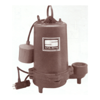
This document serves as an owner's manual for Sta-Rite Submersible, Effluent & Sewage/Solids Handling Pumps, specifically the 700E/700EH, 700S, and 900S Series. These pumps are designed for 60 Hz operation and are available in single and three-phase configurations.

Function Description:

These pumps are designed to handle various types of liquids, including effluent, sewage, and solids. They are submersible, meaning they operate while fully immersed in the liquid they are pumping. The specific series are tailored for different applications:

  • 700E/700EH Series: Primarily for effluent and sewage applications.
  • 700S Series: Designed for sewage and solids handling.
  • 900S Series: Also for sewage and solids handling, likely with higher capacities or different performance characteristics than the 700S series.

The pumps are intended for permanent installation in a vertical position within a basin. They operate by moving liquid from a lower level to a higher discharge point, preventing backflow with the use of check valves. Automatic operation is typically achieved through float switches or pump controllers, which activate and deactivate the pump based on liquid levels.

Important Technical Specifications:

The manual provides detailed electrical specifications for each series, including horsepower (H.P.), voltage/frequency (Voltage/60 Hz), phase, and required individual branch circuit amperage.

700E/700EH Series:

  • 1/2 H.P.: 115/230V, 1-phase (15/10 Amps); 208-230/460V, 3-phase (10/6 Amps).
  • 1 H.P.: 230V, 1-phase (15 Amps); 208-230/460V, 3-phase (10/6 Amps); 380V, 3-phase (6 Amps).
  • Specific models like PWE7E14-02 (1 H.P., 380/3) have a full load amperage of 3.7A, and PWEH7E14-02 (1 H.P., 380/3) has 3.8A.

700S Series:

  • 1/2 H.P.: 115/230V, 1-phase (15/10 Amps); 208-230/460V, 3-phase (6/3 Amps).
  • 3/4 H.P.: 115/230V, 1-phase (15/10 Amps); 208-230/460V, 3-phase (6 Amps).
  • Specific models like PWS7C01W2-04 (1/2 H.P., 115/1) have 11.2A, and PWS7D01W2-04 (3/4 H.P., 115/1) have 12.0A.

900S Series:

  • 3/4 H.P.: 230V, 1-phase (10 Amps); 208-230/460V, 3-phase (10/6 Amps).
  • 1 H.P.: 230V, 1-phase (15 Amps); 208-230/380/460V, 3-phase (15/10/6 Amps).
  • 1-1/2 H.P.: 230V, 1-phase (15 Amps); 208-230/380/460V, 3-phase (15/10/6 Amps).
  • 2 H.P.: 230V, 1-phase (20 Amps); 208-230/380/460V, 3-phase (15/10/10 Amps).
  • Specific models like PWS9E02W2-05S (1 H.P., 230/1) have 8.5A, and PWS9G02W2-05S (2 H.P., 230/1) have 13A.

Piping Requirements:

  • Discharge pipe must not be smaller than pump discharge.
  • For sewage systems, pipe must handle 2" (51mm) semi-solids.
  • For effluent systems, pipe must handle 3/4" (19mm) semi-solids.
  • Minimum flow rate in discharge line: 2 feet per second (61 cm/sec).
    • 2" (51mm) pipe: 21 GPM (79.5 L/M)
    • 2-1/2" (64mm) pipe: 30 GPM (113.5 L/M)
    • 3" (76mm) pipe: 48 GPM (182 L/M)
  • A check valve (2" min. for sewage, 1-1/2" min. for effluent) is required to prevent backflow. It should be a free-flow type that passes solids easily and should not be installed more than 45° above horizontal or in a vertical position.
  • A 3/16" (5mm) vent hole should be drilled in the discharge pipe 1-2" (25-50mm) above the pump discharge connection (but below the check valve) to prevent airlocking.

Installation Requirements:

  • Pump must be installed in a vertical position only. Incorrect installation voids the warranty.
  • Install on a hard, level surface (cement, asphalt, etc.), never directly on earth, clay, or gravel.
  • Basin must be at least 18" (458 mm) in diameter and 30" (762 mm) deep.
  • Local codes must be checked and complied with, including venting sewage or septic tanks.
  • Do not install in hazardous locations as classified by National Electrical Code, ANSI/NFPA 70-1984.
  • For single-phase pumps with cord and plug, plug into a grounded outlet with its own individual branch circuit. For system control, connect pump ground lead to system ground.
  • Three-phase pumps are for permanent connection only. Strain relief must be provided at the control box. Only qualified personnel should install and service three-phase pumps and associated control equipment.
  • Ensure power supply information (Voltage/Hertz/Phase) on the pump motor nameplate matches incoming power supply exactly.

Usage Features:

  • Automatic Operation: Pumps can be connected to automatic float switches or pump controllers. Float switches are factory-set with a 4" tether length, which can be adjusted. The liquid level must remain a minimum of 2" above pump suction at the lowest level and below the basin inlet pipe at the highest level.
  • Continuous Operation: Pumps can be wired directly into an electrical outlet or switch box for continuous operation, connected to their own individual branch circuit.
  • Overload Protection (Single Phase): Automatic overload protectors prevent motor burnout from overheating/overloading. The protector automatically resets and restarts the motor once it cools. Frequent tripping indicates potential issues like a stuck impeller, wrong/low voltage, or electrical failure.
  • Overload Adjustment (Three Phase): For pumps with a nameplate service factor of 1.0, the overload protective device should be set to the nameplate full load current. For pumps with a service factor of 1.15 or higher, it should be set to 1.09 times the nameplate full load current. The trip current should be 115% of this final setting.

Maintenance Features:

  • Lubrication: Pumps are permanently lubricated and require no oiling or greasing in normal operation.
  • Cooling: The pump normally runs hot. Allow 20 minutes for cooling after shut-down before handling.
  • Dry Running: Do not run the pump dry, as this can cause overheating and void the warranty.
  • Servicing:
    • Always disconnect electrical power to the pump and control switch before servicing to avoid electrical shock, burns, or death.
    • Do not lift the pump by its power cord; use the lifting ring or handle. Lifting by the cord can damage connections, expose bare wires, and void the warranty.
    • After removing the basin cover and discharge piping, lift the pump out of the basin.
    • Clean the pump thoroughly, removing all scale and deposits.
    • Submerge the pump in disinfectant (chlorox or chlorine) for at least one hour before disassembling.
    • The motor housing contains special lubricating oil. Keep oil clean and free of water.
    • When the motor cover is removed for service, the oil should be removed and replaced with new dielectric oil (Part No. U197-8A) during reassembly. Do not overfill; the oil level with a cold motor should be about 1/4" (6 mm) above the top of the motor assembly to allow for expansion.
    • Impeller, Seal, and Capacitor Replacement (700E/700EH/700S Series):
      • Disassembly involves unscrewing hex-head cap screws, removing the motor assembly from the volute, draining oil, removing the impeller nut and washer, and unscrewing the impeller.
      • Capacitor Discharge: Before touching the capacitor (single-phase only), discharge it by shorting the terminals together with an amber-handled screwdriver to avoid electric shock.
      • Further disassembly includes loosening the cord nut, disconnecting wires, unfastening socket head screws, and removing the motor cover and seal plate.
      • Reassembly requires pressing a new seal body into the seal plate cavity (using Permatex #2 sparingly on the outside edge of the seal body), reinstalling the motor and shaft, sliding the new rotating half of the seal onto the shaft (being careful not to nick or scratch the carbon seal face), reassembling the impeller, washer, and impeller nut, installing a new capacitor, inspecting and reinstalling the O-Ring (or replacing if damaged), reinstalling the capacitor cover, and filling the motor with dielectric oil.
    • Impeller, Seal, and Capacitor Replacement (900S Series):
      • Disassembly involves removing hex head bolts, impeller screw and washer, sliding the impeller off the shaft, unfastening hex head screws holding the capacitor cover, disconnecting wires, draining oil, removing the capacitor (if applicable), prying out the lip seal, removing the retaining ring and washer, and removing the motor cover and seal plate.
      • Reassembly requires pressing a new primary seal head into the cavity (using Permatex #2 sparingly), setting the seal plate on a cradle, reinstalling the motor, inspecting and replacing the seal plate O-Ring, sliding the new rotating member of the seal onto the shaft (applying soap to the rubber ring), reinstalling the washer and snap ring, installing a new lip seal (lubricating with Aqualube or lithium-based grease), reassembling the impeller, washer, and impeller screw, reinstalling the capacitor (single-phase only), filling the motor with dielectric oil, inspecting and replacing the capacitor cover O-Ring, and reconnecting motor lead wires.
  • Troubleshooting: The manual provides a "Troubles-Remedies" section for common issues like the pump failing to operate, failing to empty the sump, or failing to shut off. Remedies include checking power connections, electrical power, liquid level, vent hole blockage, pump inlet/impeller/check valve/discharge pipe blockage, and thermal overload trips. For persistent issues, consulting a local serviceman is recommended.

STA-RITE 700E Series Specifications

General IconGeneral
BrandSTA-RITE
Model700E Series
CategoryWater Pump
LanguageEnglish

Related product manuals