BS and BSA Bias Supply Series and User Manual, Rev 2.60
www.stahl-electronics.com phone: +49 6242-504882, fax: +49 6242 504884
12
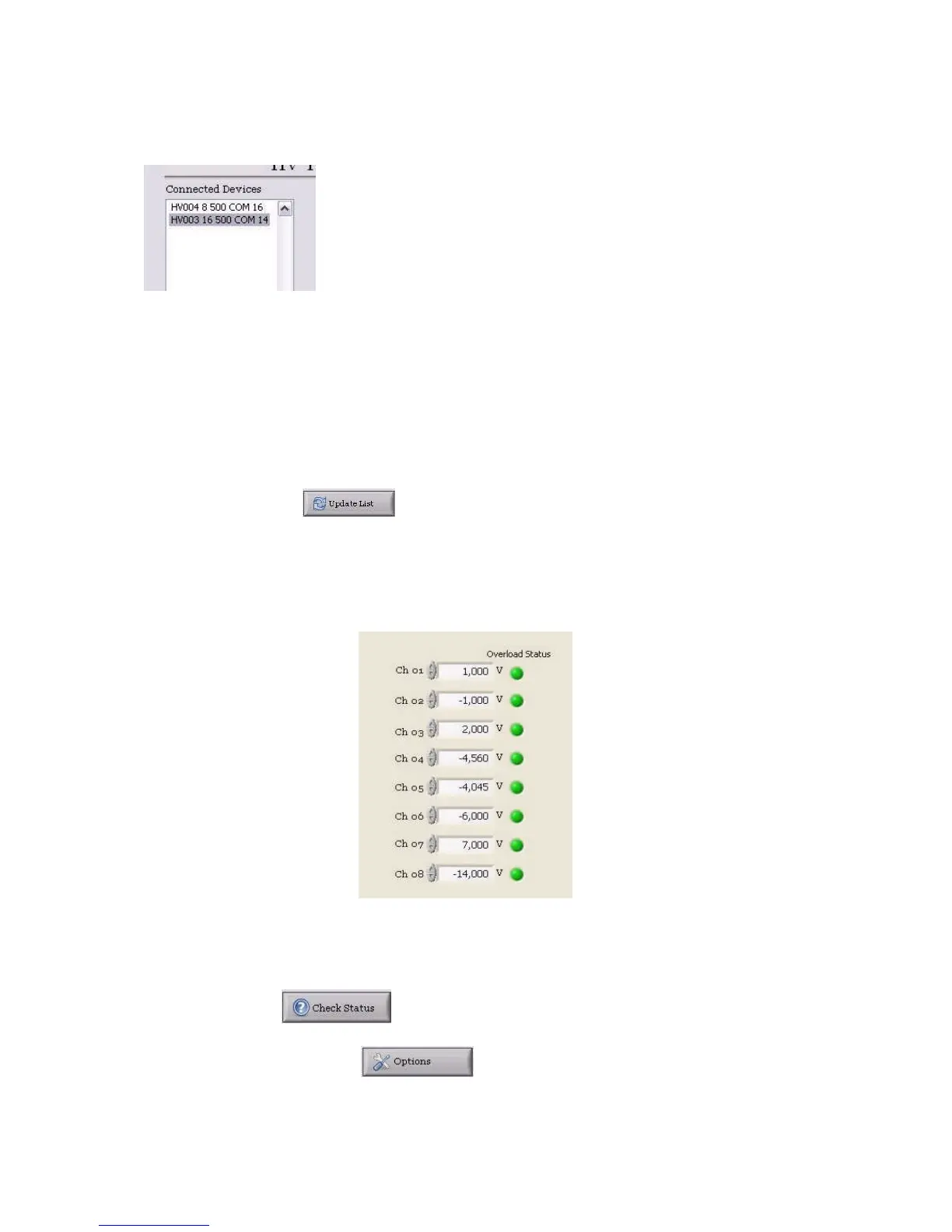
While starting up, a list of connected devices (upper left corner) will be updated and the program will
list all recognized HV- and BS-Series devices inside the window. Please note, that before taking any
action the user may click once on a listed device to select this one for further operation.
picture shows a list with two recognized devices inside the displayed list.
The information about the listed devices shows:
- device serial number (e.g.: HV021, for a device with serial number 021)
- the number of available channels on that specific device
- the voltage rating (e.g. 10V), including overrange
- the COM port number, under which the device will be accessible in Microsoft Windows from
the PC.
Note, that the driver software on a Windows
TM
PC will enumerate detected USB devices
automatically. This COM port number may vary from PC to PC and does not depend on the connected
device itself.
If a new device is connected while the program is already running, the list can be forced any time to be
updated by pressing the button.
Note also, that the correct device communication speed (mostly 9600 Baud or 115200 Baud) must be
selected with the corresponding selection tab. In case the communication speed has been changed one
may also press the ‘Update List’ button again in order to check the physical connections at the PC.
Next right to the list of connected devices the user can set the voltages of each channel in the
numerical control field, either manually by entering numbers or by clicking on the up/down arrows. A
step size can be defined in the control field underneath the voltage input controls fro convenience .
At right hand side besides the numerical control field for the voltages, the “Overload Status
Indicators” appear. They indicate the status of the circuitry for every channel. As long as the set
voltage can be held, the indicator is green. If the pre-defined over-current value of approx. +/-8.6mA is
exceeded, it will lighten up red. Depending on LabVIEW settings the control program reads the actual
status over the USB bus roughly once per second. A forced and immediate status check is possible, if
the user clicks on the button.
By pressing the Options Button , the user can manually read the device’s internal
temperature in the subsequent window or enter manually commands to the device (for advanced users,
see also the list of commands in the appendix).



 To Next Page