BS and BSA Bias Supply Series and User Manual, Rev 2.60
www.stahl-electronics.com phone: +49 6242-504882, fax: +49 6242 504884
3
1. General Information and Overview
1.1 Purpose and Description of the Device
BS and BSA Series devices provide precise and stable DC voltages up to +/-14V (depending on device
version) for biasing and for general purposes. Unlike DC power supplies, the outputs currents are
limited to small values, and the outputs are optimized for high short and long term stability, low noise
and low temperature drift. The device is housed in a standard 19-inch rack-mount case. User control of
the device is accomplished by PC control programs, utilizing a standard USB connection (USB 2.0
compatible). The programmed voltages and measured output currents are displayed on the front LCD
display. BS and BSA devices differ mainly with respect to the internal voltage resolution (BS: 16Bits,
BSA: 19 Bits). On both version the measured output voltages and currents can be read back, which
allows the devices to be used as source-meter units.
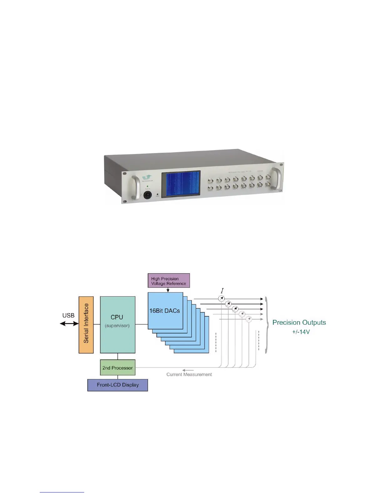
1.2 Functional Principle and Block Diagram
The following picture displays the internal structure. A USB interface receives commands from a PC,
which are translated into output voltages on 8, 10 or 16 channels. Voltages and corresponding output
currents are displayed on the front display. In case an output is not able to establish the desired
voltage, or if a current overload occurs, indicators on the user interface will signal a malfunction. All
outputs can deliver both voltage and current polarities, negative as positive (4-quadrant operation).
Fig. 1.1: Illustration of internal structure (simplified, BS version)