BS and BSA Bias Supply Series and User Manual, Rev 2.60
www.stahl-electronics.com phone: +49 6242-504882, fax: +49 6242 504884
16
and ch6 to 10 connected in the way like ch 1 to 5.
Note: The ch5/10-functionality is different in case of an installed PID loop (see chapter 7.2).
7.1 Manual Voltage Control
If the corresponding option is installed, one may choose to user either an external PC to control the
output voltages (remote-mode) or define them by adjusting a potentiometer on the front plate (manual
mode). A manual switch on each channel defines the used mode (“remote” or “manual mode”).
Figure 7.1: Individual switches for each channel allow to choose between remote control and manual control of
an output voltage.
7.2 PID Loop for Cryo Amplifiers
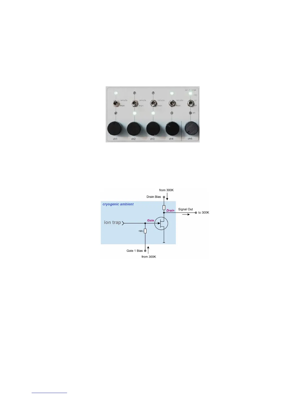
A PID Loop for cryogenic amplifiers may be implemented, which can be used to achieve stabilization
of cryogenic (e.g. 4.2K) FET-based amplifiers. This loop assumes an inverting amplifier stage like
shown in the subsequent figure. An Ion trap was assumed as signal source for example.
Figure 7.2: schematic diagram of a FET-based cryogenic amplifier
Well-know problems related to cryogenic amplifiers are temporal and thermal drifts, arising from
small temperature changes in a cryogenic environment. In setups with several amplifiers operating at
the same time the biasing adjustment can be highly complex since the adjustment of one channel may
affect neighbouring ones by thermal coupling or parasitic DC-currents on the GND-line.
An effective countermeasure is the use of an automatic stabilization loop, which keeps the Drain DC-
voltage of individual FETs, and thus their Drain current and power dissipation constant. Such loops
are provided in the BS series supply in case the corresponding option is chosen. 2 loops are
implemented per device. The subsequent figure shows the wiring principle.



 To Next Page