BS and BSA Bias Supply Series and User Manual, Rev 2.60
www.stahl-electronics.com phone: +49 6242-504882, fax: +49 6242 504884
17
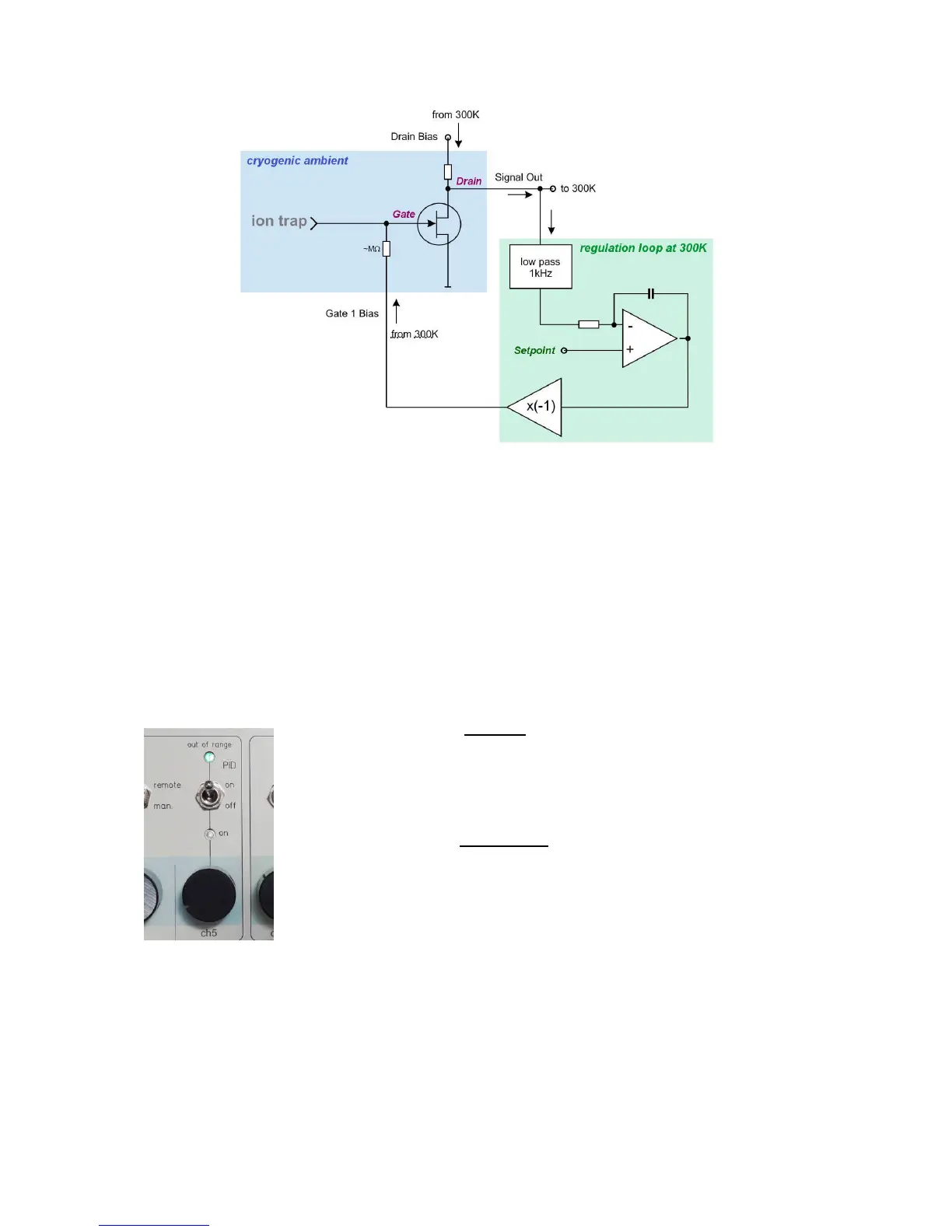
Figure 7.3: scheme of a cryogenic amplifier and a slow feedback loop to maintain Drain voltage stability.
The used circuit employs operational amplifiers to generate the FET Gate 1 control voltage (channels
1 and 6 of the BS supplies). The DC level of the Drain output voltage is measured (PID input at rear
side) and compared with a setpoint voltage. This setpoint is manually adjusted by the channel 5 (and
10) potentiometer on the front plate. It can be measured at the corresponding BNC output sockets at
the rear side (5 and 10). The voltage difference between setpoint and read-back value is translated into
a correction voltage and fed into the Gate-voltage to correct the biasing of the amplifier. This closed
loop keeps the Drain voltage constant at the setpoint level (only the DC part is used in order not to
influence AC signals of interest). The correction sensitivity has a value of approx. 10Volts/second per
Volt deviation of setpoint-Drain difference, representing the integral (“I”) part of a PID loop. E.g. at a
voltage difference of 1 Volt (setpoint to actual voltage), the Gate 1 voltage will be adapted with an
initial slope of 10V/second until the setpoint value is reached.
The position of the PID-switch (on front plate at channels 5 or 10 respectively) is decisive for the
function of channel 1 (or 6):
In case the PID-switch is activated (like shown in the photo beside) then the
internal PID loop regulates the output voltages on channel 1 (or 6 respectively)
at the rear side. Changes on the potentiometer on channel 1 (or 6) or a command
on channels 1 or 6 have no effect at all. Only the setpoint determined by the
potentiometer at channel 5 (or 10) and the measured Drain output voltage on the
PID input (rear side) causes changes of the channel 1 (or 6) output.
In case the PID-switch is not activated the internal PID loop is not active and
the output voltages available on the rear side are defined in the normal way by
the potentiometer (in manual mode) or by the remotely-controlled value
(remote-mode) respectively. The green “range ok” indicator lightens up, if the
PID-loop correction voltage (outputs 1 and 6) resides within a voltage range of -
2.8V to +0.25V and becomes dark, otherwise.
figure 7.4: The position of the PID-switch activates/deactivates the internal PID loop.
The subsequent picture shows an example of the numbers seen in case of the PID usage (PID loop 1,
affecting channels 1, 4 and 5). In this case channel 4 was used as Drain supply voltage, for example set
to about 3.95V (white circle in screen shot below). The PID loop was activated with the PID-switch
and the set point of Drain output voltage set to 1.515V with the potentiometer below the PID-switch.
The read back value of the potentiometer setting is shown in the channel 5 reading, marked with green
circle below in fig. 7.5. In order to hold this set point value, the loop regulated the gate voltage to -
1.829V (red circle in fig. 7.5). The correct functionality of the loop can be monitored by checking the
read back value of the loop voltage (being applied to the PID input at rear side), e.g. 1,502V in this



 To Next Page