BS and BSA Bias Supply Series and User Manual, Rev 2.60
www.stahl-electronics.com phone: +49 6242-504882, fax: +49 6242 504884
18
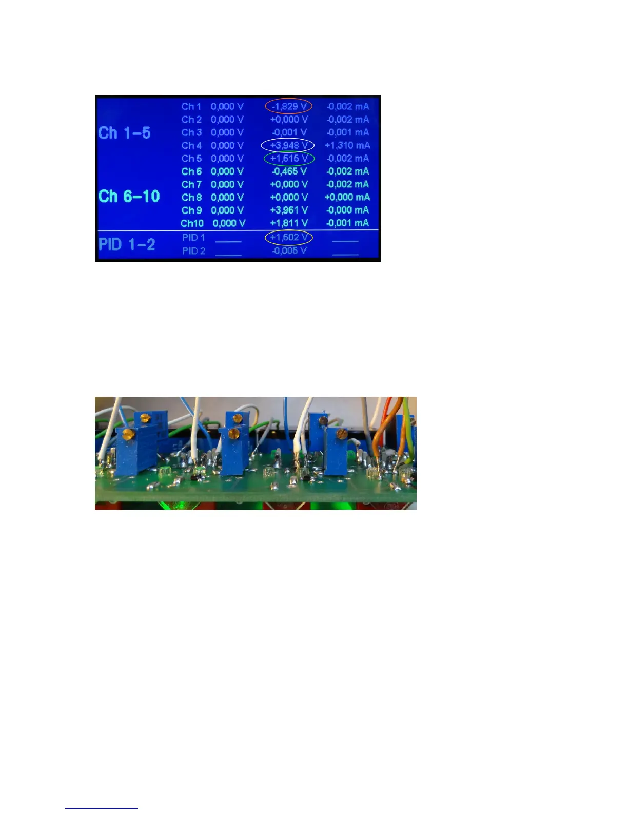
example (yellow circle), which should be equal to the set point, and is indicated also by green LED
light above the PID switch.
fig . 7.5 Screen shot photograph using the PID loop 1.
7.3 Output Voltage Limitation
For safety reasons the BS devices intended for supplying cryogenic electronics/amplifiers are
equipped with a possibility, which allows the user to set limits to the output voltages. These limits
apply regardless whether the manual or PC-controlled mode is chosen. The voltage limits are set using
conventional potentiometers. In order to access them one has to open the device lid. Behind the front
plate there are 20 variable resistors, which are adjusted with a normal screwdriver.
fig . 7.6 Photograph of set-limit potentiometers behind the front plate.
The upper row of potentiometers defines the maximum (normally i.e. positive) value of output
voltage, the lower row defines the most negative voltage. Assignment to channel numbers is from left
to right from 1 to 10, as it is intuitively clear. In order to adjust a potentiometer, let’s say e.g. an upper
one, one may set the most positive voltage (remotely or manually) and turn the adjustment screw until
the output shows the desired maximum voltage. Proceed with the negative limits accordingly. Please
note that if the output voltage approaches the set limit, there is a transition region of about 0,4V
magnitude, during which the actual voltage will increasingly deviate from the set value. This
represents a “smooth” transition from the set voltage to the limiting value.



 To Next Page