BS and BSA Bias Supply Series and User Manual, Rev 2.60
www.stahl-electronics.com phone: +49 6242-504882, fax: +49 6242 504884
13
4.3 Output Characteristics
General properties
The device features stable bipolar low-current DC voltage outputs with low noise, ripple and low
temperature drifts. The outputs are of four-quadrant-type, i.e. they can both sink and source currents
regardless of the output polarity. Heavy external loads should be avoided, which reach or exceed the
device‘s nominal output current of 10mA on a longer time scale (minutes, hours).
The outputs feature an internal programming resolution of 16 Bits (BS series) or 19 Bits (BSA series).
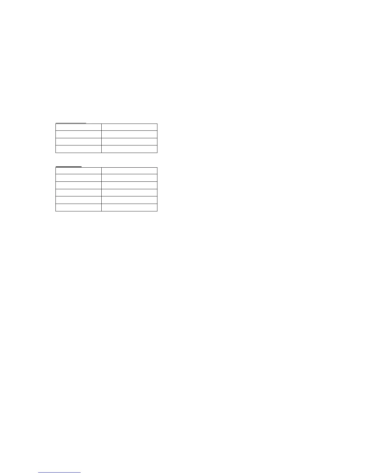
This translates into these approximate resolutions:
BSA series:
output range approx. resolution
+/-14V 50µV
+/-10V 40µV
+/-5V 20µV
BS series:
output range approx. resolution
+/-14V 500µV
+/-10V 300µV
+/-5V 150µV
+/-1V 30µV
+/-100mV 3µV
The output reacts on voltage change commands after a delay (see appendix) depending on the speed
mode and with an analog signal rise time (10%-90%) of typically 20µs.
Output accuracy, fluctuations and loads
Precision components ensure a very good base accuracy and very low long-term drift, both on a 10
-4
to
10
-5
level and below. Intrinsic short term stability is on a level of several µVolts, corresponding to
only a few ppm’s (parts per million) with respect to the full voltage span (devices with span greater +/-
1V). For details about 12h and 24h-fluctuations see also technical data in section 8 and fluctuation
data in section 9, showing the behaviour of the +/-10V-version. Devices featuring other output
voltages behave similar, fluctuations essentially scale with the output voltage span.
All outputs feature protection resistors serially to the internal output amplifiers (50, details see
specification) which will cause a voltage drop as soon as current is drawn from any output. Please take
into account that voltage drop (according to Ohms law) for operation with considerable load currents
or for high precision measurements. Heavy capacitive loads (>2µFarad) should be avoided for stability
reasons, especially in conjunction with very long cabling (> 20m). In cases where higher capacitive
loads or longer cabling is required, the addition of about 20 Ohms in each line will ensure better
stability. You may also contact manufacturer in cases with longer cabling or heavier loads in order to
adapt the output properties accordingly.
Short cuts or other heavy loads at the outputs
Generally all outputs are short-cut proof, with respect to GND-short cuts or short cuts to any voltage
between the specified min./max. voltage. Nevertheless shortcuts represent a thermal load on the
internal output stages and may impair their life expectance, in case present for longer times. This holds
especially, when the optional floating offset input is used (see chapter below), which may increase the
current flowing in case of a short cut event considerably. Externally applied offsets larger than +/-5 V
therefore may damage the outputs in case of a short cut event, due to excessive thermal load on the
output stages.



 To Next Page