Do you have a question about the Stahl SLE 3 and is the answer not in the manual?
Provides context for the SLE 3 control unit's use as a safety manual for hoist operations.
Details consequences of non-compliance with operating instructions, affecting liability and warranty.
Explains safety symbols used in the manual for hazard severity and specific warnings like electrical voltage or hand injuries.
Identifies electrically skilled persons and competent persons responsible for installation, troubleshooting, and maintenance.
Lists prerequisites for warranty fulfillment, including adherence to operating instructions and intended use.
Warns against using the device contrary to instructions, which voids warranty.
Emphasizes the need for programming and documenting commissioning for safety functions.
Lists relevant European directives and standards for hoists and the SLE 3 control equipment.
Defines the SLE 3's specific applications, limitations, and role in hoist control and overload protection.
Outlines guidelines for electrical installation, cabinet assembly, wiring, and cable connections for safe operation.
Details potential hazards like unexpected start-up and direct contact with power supply, requiring safety precautions.
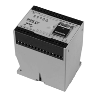
Introduces the SLE 3 as an electronic control unit for hoists with overload cut-off and monitoring functions.
Explains the role of the DMS load sensor, its importance as a safety component, and requirements for approved sensors.
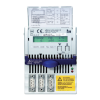
Illustrates the SLE 3's front panel, identifying switches, display board, and signalling/status LEDs.
Presents a block diagram showing the internal components, connections, and signal flow of the SLE 3 unit.
Displays the schematic circuit diagram of the SLE 3, illustrating power supply, load sensor, and output connections.
Details the safety functions of the SLE 3, focusing on overload cut-off mechanisms and response times.
Explains the overload cut-off design, conditions for activation, and response times according to ISO 13849-1.
Describes detected sensor errors (broken cable, short circuit, differential), their consequences, and detection times.
Introduces the control and monitoring capabilities of the SLE 3, including actuation and relay outputs.
Explains motor management functions, including off-times for lifting and lowering movements based on switch settings.
Presents a table detailing motor management parameters and their relationship to settings (S1, S3) and times (ts, tf, tr, ta, tb).
Describes the integrated operating time counter that logs the total hours of hoist motor actuation.
Details the temperature monitoring function for hoist and travel motors via thermistor inputs, including error indication and blocking.
Explains the parameterization and use of 'err' and 'option' signaling relays for outputting error messages.
Provides the physical dimensions of the SLE 3 unit (W x H x D).
Describes methods for attaching the SLE 3, including snap-on and screw mounting.
Specifies mounting requirements, recommending installation in a switch cabinet with at least IP 54 protection.
Details the requirements and types of tests (acceptance, regular) for the SLE 3, emphasizing qualified personnel.
Explains how to save a new cut-off point using the testing bay function, requiring an electrically skilled person.
Introduces the settings section, including the testing bay function and permissible cut-off point range.
Describes the testing bay function, its purpose for setting overload cut-off, and associated safety warnings.
Provides a step-by-step guide for activating the testing bay function, including switch settings and LED indications.
Explains the purpose and activation of the "Crane test" function to increase the overload cut-off point for specific testing.
Details the preparation and activation procedure for the "Crane test" function, requiring specific switch operations and timing.
Outlines methods for deactivating the "Crane test" function, such as restarting the device or pressing button S5.
Provides a table for documenting changes to the cut-off point, requiring signatures and confirmation to maintain warranty.
Guides on replacing the device or sensor, emphasizing restoration of original installation state and re-commissioning.
Advises on regular maintenance, specifically checking screw terminal tightness annually.
States that the SLE 3 has no wear parts and outlines properties for equivalent replacement devices.
Describes the operational status indication using LEDs (pwr, err, I, II, III) and general error handling.
Details error states detected by the SLE 3, their consequences (e.g., lifting blocked), and correction methods.
Explains warning messages indicated by LEDs, their causes (e.g., crane test active, overheating), and corrective actions.
Outlines operator responsibility for decommissioning, environmental laws, and disposal of electronic scrap.
Lists supply voltage variants, tolerance, power consumption, and fuse protection for the SLE 3.
Provides technical specifications for the load sensor input, including type, supply voltage, and signal range.
Lists safety parameter values for the SLE 3 according to ISO 13849-1.
Covers EMC standards, operating/storage temperatures, dimensions, protection, and mounting.
Details connection terminals, attachment, weight, mounting position, and maximum cable lengths for signals.
Lists safety parameter values for sensors and contactors according to ISO 13849-1.
Explains how to find type designation, hardware, and software versions on the rating plate.
Details the structure of the SLE device type designation and its encoded parameters.
Provides a log sheet for documenting changes to SLE 3 device settings, including signatures and reasons.
A blank section for user notes.
| Brand | Stahl |
|---|---|
| Model | SLE 3 |
| Category | Control Unit |
| Language | English |