6 Error and warning messages, faults
24 06.2017
6 Error and warning messages, faults
Testing of the electrical installation may only be carried out by an electrically skilled
person.
Changes to the overload cut-off point or a device replacement may only be carried out by
a competent person.
The detailed description of errors is to be found in the "Service instructions of the
original operating instructions".
Internal tests are carried out when the power supply is switched on. The LEDs "pwr",
"err", "I", "II", "III" light up during this test.
The SLE 3 is ready for operation when only the LED "pwr" is still on.
Symbols
LED is off LED flashes LED lights up
Device is ready for operation
6.2 Error state indicators
The SLE 3 constantly carries out internal tests and tests on the connected sensors and
monitors the plausibility of external and internal switch states. If the SLE 3 detects a
problem, an error or error state is set and lifting or lifting and lowering is blocked.
The possible errors and their indication are described in the following table and must be
corrected before further operation is possible.
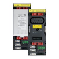
Sensor error:
Broken cable, short
circuit
Check load sensor connection: screw terminals for
tightness (-S, -IN, +IN, +S), correct wire assignment
per circuit diagram
Measure sensor supply voltage (+S / -S): set point
value 9.5…10.5 V
Measure the output voltage of the connected
sensor (-IN / -S, +IN / -S): value approx. 5 V
Measure the sensor values at the disconnected
sensor: set point values:
between wires RED / BLACK: 350 … 400
between wires BROWN / ORANGE: 346 … 356