ASSEMBLY INSTRUCTIONS
STEP 4
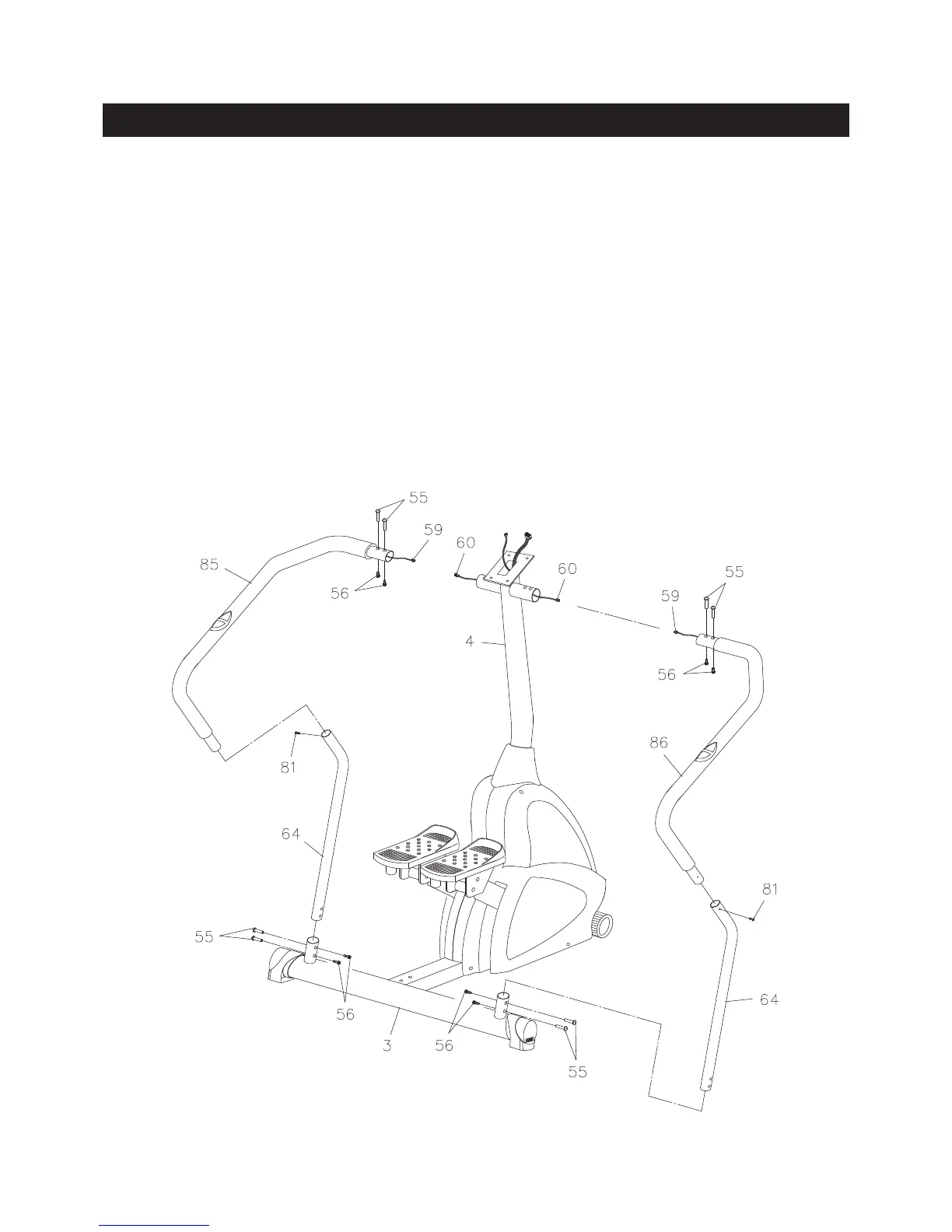
Insert the LOWER HANDRAIL(64) into the REAR STABILIZER(3). Plug the PULSE SENSOR WIRE(59)
into the PULSE CONNECTING WIRE(60), then insert the RIGHT HANDRAIL(86) into the UPRIGHT(4).
Insert the RIGHT HANDRAIL(86) into the top end of LOWER HANDRAIL(64).
STEP 5
Secure the RIGHT HANDRAIL(86) to the UPRIGHT(4) with the BARREL NUTS(M6x1)(55) and
SOCKET HEAD BOLTS(M6x1x16mm)(56). Do not tighten the bolts. Secure the RIGHT HANDRAIL(86)
to the LOWER HANDRAIL(64) with ROUND HEAD SCREW(M4x0.6x12mm)(81). Secure the LOWER
HANDRAIL(64) to the REAR STABILIZER(3) with the BARREL NUTS(M6x1)(55) and SOCKET HEAD
BOLTS(M6x1x16mm)(56). Tighten all of the bolts.
Repeat Steps 4 and 5 to attach the LEFT HANDRAIL(85) to the unit.
9