9
ASSEMBLY INSTRUCTIONS
L
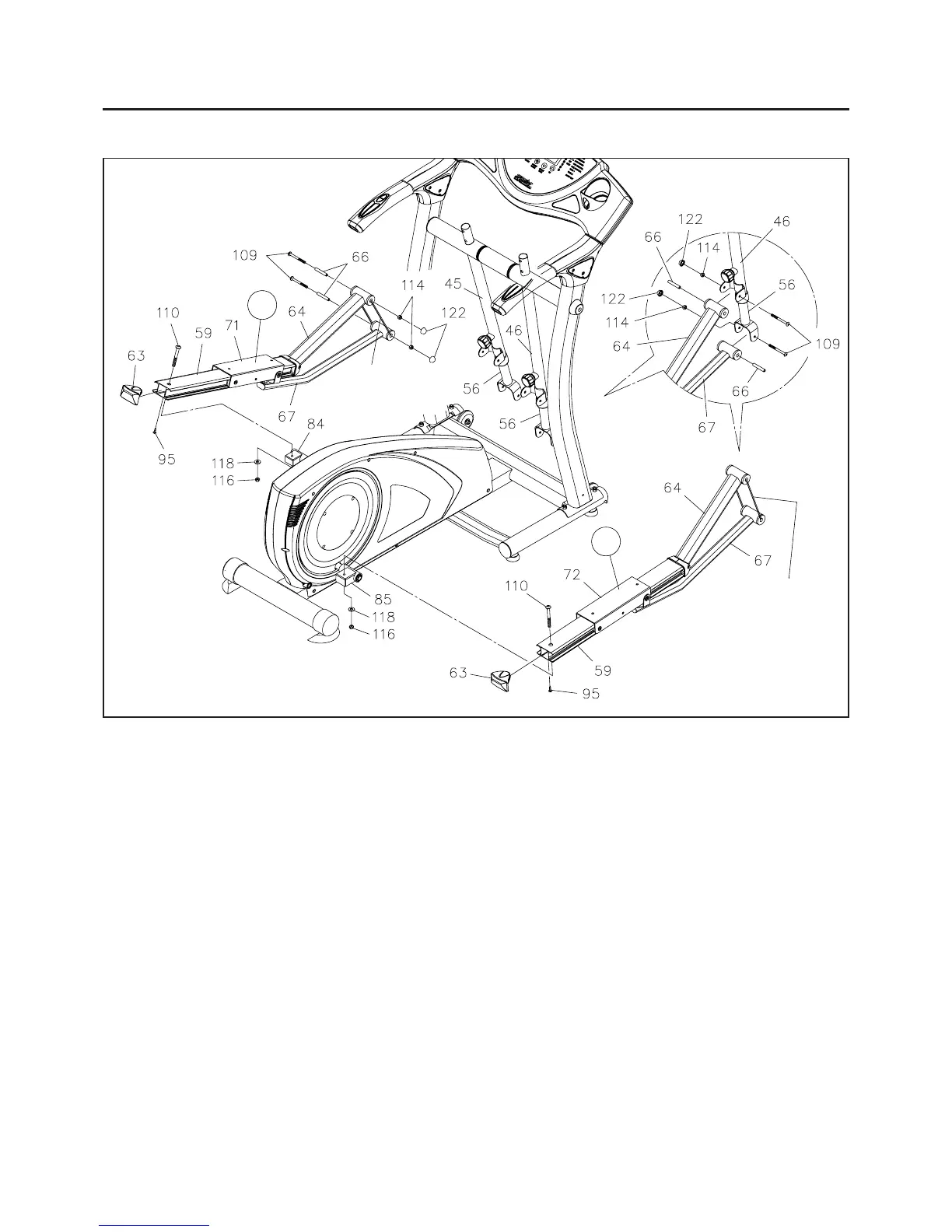
STEP 12: Refer to the inset drawing. Insert the SHAFT SLEEVE(66) into the SUPPORT ARM(64).
Attach the SUPPORT ARM(64) at right side to RIGHT PIVOTING ARM(46) with BUTTON HEAD BOLT
(M8x1.25x90mm)(109) and NYLOCK NUT(M8x1.25)(114). Insert the SHAFT SLEEVE(66) into the
LINKAGE(67). Attach LINKAGE(67) at right side to TELESCOPING BAR(56) in the RIGHT PIVOTING
ARM(46) with BUTTON HEAD BOLT(M8x1.25x90mm)(109) and NYLOCK NUT(M8x1.25)(114). Press a
NUT CAP(122) onto each NYLOCK NUT(M8x1.25)(114). Repeat on the left side.
R
Do not cut off the
tie until STEP 12.
Install the right PEDAL RAIL ASSEMBLY by attaching the PEDAL RAIL(59) to the RIGHT RAIL
CONNECTOR(85) with BUTTON HEAD BOLT(M10x1.25x85mm)(110), WASHER(M10)(118), and NYLOCK
NUT(M10x1.25)(116). Repeat on the left side.
NOTE: The RAIL CONNECTORS(84, 85) must face toward the back as shown in the illustration above.
STEP 10
NOTE: An "L" decal identifies the LEFT PEDAL SLIDER(71) and an "R" decal identifies the RIGHT
PEDAL SLIDER(72).
The RIGHT PEDAL SLIDER(72) is attached to the right PEDAL RAIL ASSEMBLY. Attach the right PEDAL
RAIL ASSEMBLY to the right side of the elliptical unit. Attach the LEFT PEDAL SLIDER(71) and PEDAL
RAIL ASSEMBLY to the left side of the elliptical unit in the same manner.
STEP 11: Press the RAIL CAPS(63) into the PEDAL RAILS(59) and secure with ROUND HEAD SCREWS
(M5x20mm)(95).
Do not cut off the
tie until STEP 12.