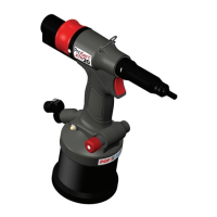
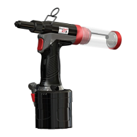
3. Tool Setup
IMPORTANT - READ THE SAFETY RULES ON PAGE 9 & 10 CAREFULLY BEFORE PUTTING INTO
SERVICE.
Before Use
• Select relevant size nose equipment and install.
• Connect the placing tool to the air supply. Test pull and return cycles by depressing and releasing the
trigger 12.
• Set the tool for desired stroke/pressure.
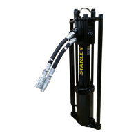
CAUTION - correct supply pressure is important for proper function of the installation tool. Personal injury or
damage to equipment may occur without correct pressures. The supply pressure must not exceed that listed in the
placing tool specication.
4. Operating Instructions
IMPORTANT - READ THE SAFETY RULES ON PAGE 9 & 10 CAREFULLY BEFORE PUTTING INTO
SERVICE.
IMPORTANT - THE AIR SUPPLY MUST BE TURNED OFF OR DISCONNECTED BEFORE FITTING OR
REMOVING THE NOSE ASSEMBLY.
4.1 Nose Equipment (see Fig.2).
Fitting Instructions
Item numbers in bold refer to nose assembly components in g 1.
• Air supply must be disconnected.
• If still tted, remove the Nose Casing 13 and the Chuck Nut 14 while pulling back the spring loaded Nose
Rod 73.
• Insert Drive Shaft E into Mandrel Adaptor 15.
• Fit Mandrel A onto Drive Shaft E.
• Insert Reducing Sleeve D (if specied) into the Chuck Nut 14.
• Screw the Chuck Nut 14 onto the Mandrel Adaptor 15 while pulling back the spring loaded Nose Rod 73.
Tighten the Chuck Nut 14 clockwise.
• While holding the Tool, screw on the Nose Casing 13 and Nose Tip B with the nose tip Lock Nut C.
• The reverse operation is carried out for equipment removal.
With the tool still disconnected from the air supply, screw a Blind Rivet Nut onto the Mandrel manually.
• Position Nose Tip B on the Nose Casing and lock it with Lock Nut C so that the Mandrel A protrudes
slightly beyond the insert.
• Lock the Lock Nut C by turning clockwise with a spanner*. Remove the Blind Rivet Nut from Mandrel.
*Refer to items included in the Maintenance Kit 07900-09301 page 16.
13
ENGLISH

 Loading...