6
ENGLISH
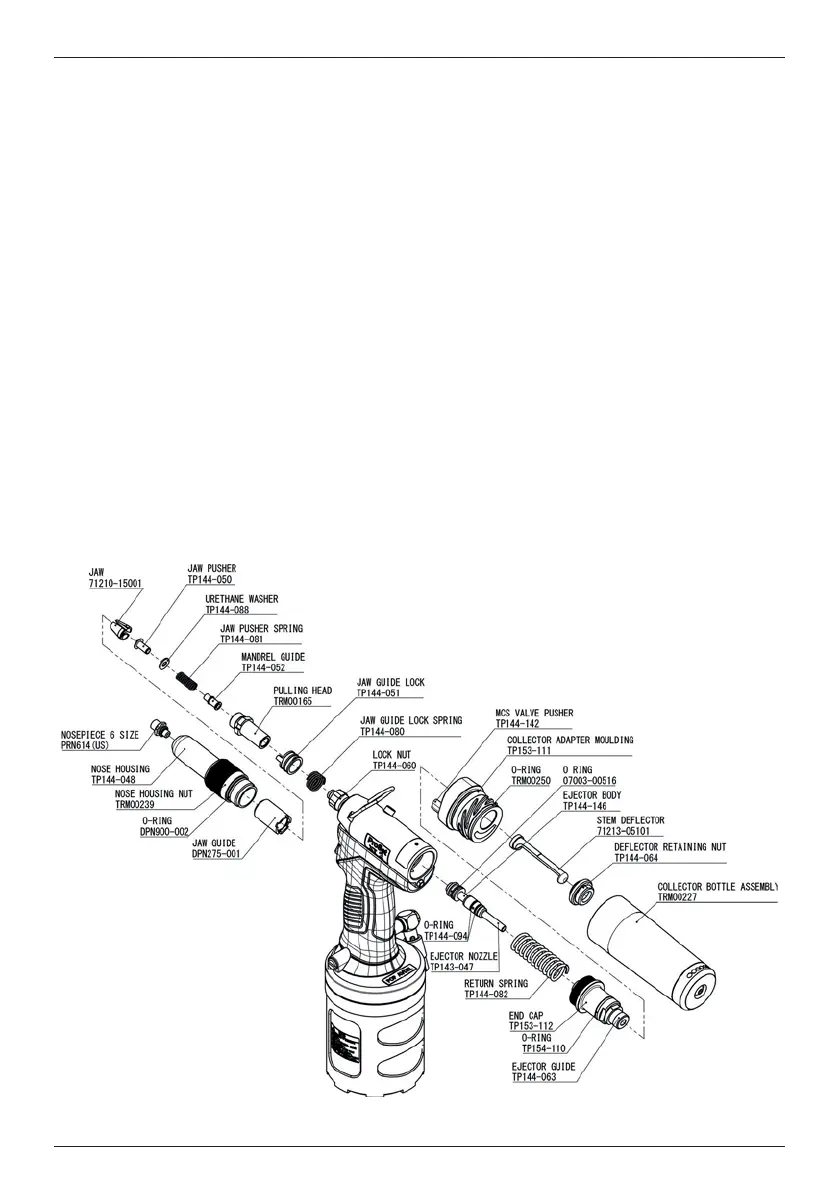
• Remove Return Spring (TP144-082) and Ejector Nozzle (TP143-047), Ejector Body (TP144-146) together
with O-Ring (TP144-094), O-Ring (TP144-094).
• Rotate Nose Housing (TP144-048) anti-clockwise and remove together with Nosepiece and Nose Housing
Nut (TRM00239).
• Rotate Jaw Guide (DPN275-001) anti-clockwise and remove together with Jaw (71210-15001).
• Remove Jaw Pusher (TP144-050) together with Urethane Washer (TP144-088), Jaw Pusher Spring (TP144-
081) from Pulling Head (TRM00165).
• Remove Mandrel Guide (TP144-052) from Pulling Head (TRM00165).
• Rotate Lock Nut (TP144-060) anti-clockwise with locked Pulling Head (TRM0165).
• Remove Pulling Head (TRM0165) together with Jaw Guide Lock (TP144-051), Jaw Guide Lock Spring
(TP144-080).
• Attach Jaw Spreader Housing (71210-02101) to Hydraulic Piston Adaptor (TRM00123).
• Attach Swivel Head Connector (TRM00496) to Handle Upper Assembly (TRM00222).
• Screw Piston Adaptor (TRM00123) to Hydraulic Piston by hand.
• Screw Lock Nut (TP144-060) to Hydraulic Piston Adaptor (TRM00123) by wrench.
• Install Ejector Assembly (TRM00494) and Return Sprong (TP144-082).
• Screw End Cap (TP153-112) together with O-Ring (TP154-110), Ejector Guide (TP144-063).
• Fit Collector Adaptor (TP153-111) together with MCS Valve Pusher (TP144-142).
• Place Collector Adaptor Cover (TRM00033) over Collector Adaptor (TP153-111) and then install Cover
Retaining Nut (TRM00090) until the end face of Collector Adapter Cover (TRM00033) is secure against the
mating face of Collector Adapter (TP153-111).
• The tool is now ready to be tted with aswivel head.
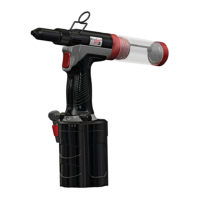
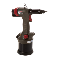
Item numbers in bold refer to g. 5 and g. 6 and the table on page 6.
Fig. 5