8
ENGLISH
SWIVEL HEAD FITTING INSTRUCTIONS
IMPORTANT - READ THE SAFETY WARNINGS LISTED IN THE PROSET XT1 AND PROSET XT2 INSTRUCTION
MANUAL CAREFULLY BEFORE PUTTING INTO SERVICE.
IMPORTANT - THE AIR SUPPLY MUST BE TURNED OFF OR DISCONNECTED BEFORE FITTING OR
REMOVING THE SWIVEL HEAD NOSE ASSEMBLIES.
The following procedure will allow you to
assemble and t either of the swivel heads to
the tool. If you order acomplete swivel head
rather than individual components, you will
only need to start at step ‘L’.
All moving parts should be lubricated. Unless
stated otherwise use Moly Lithium grease. Text
highlight in grey tint refer only to the right-
angle swivel head tting instructions.
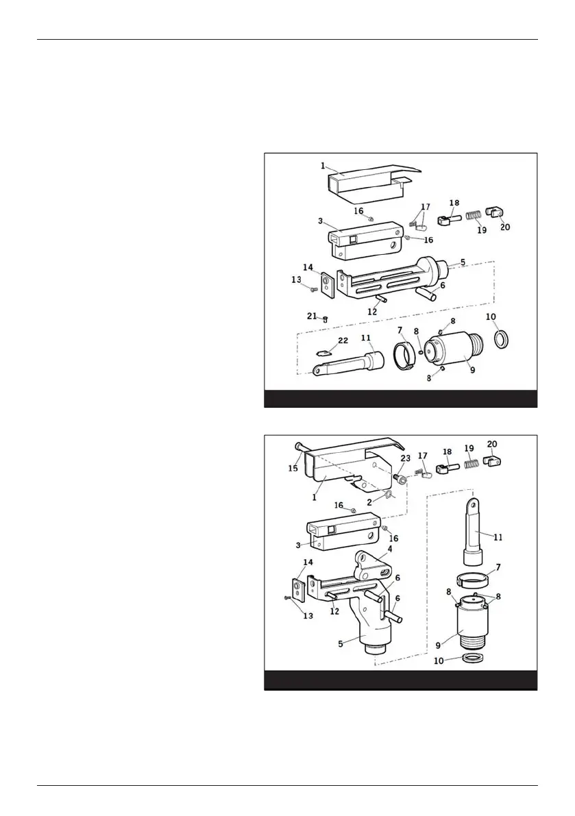
Item numbers in bold refer to the components
in gures 7 and 8 and the table on page 6.
Note: Nose Tips (14) Jaws (17) vary to suit
speci c rivet. Refer to the table 1 and Table 2
to select the correct nose tip for the rivet being
installed.
A. Fit Locking Ring 10 over Jaw Spreader
Housing (24).
B. Coat Screw (13) with thread locking
adhesive and use to secure Nose Tip (14)
onto Body (5).
C. Lightly lubricate items (17), (18), (19), (20)
and insert into Jaw Carrier (3) as shown.
Secure with Screws (16).
D. Position Lever (4) into Body (5) and hold
in place with pin (15) through the hole of
Body (5) (not aslot).
E. Lubricate the sides of the Jaw Carrier
Assembly and insert into Body (5).
F. Lubricate Rollers (8) and ENSURE that they
will freely rotate in the holes of Adaptor (9).
If necessary ream the holes.
G. Position Spring Clip (7) over Adaptor (9)
past the holes for the rollers and rotate
until the locating peg is aligned with the
corresponding hole in Adaptor (9) (smallest
hole).
H. Fit Adaptor (9) over the end of Body (5) and
drop Rollers (8) into place. Push Spring Clip
(7) over Rollers (8).
Fig. 7
Fig. 8
STRAIGHT SWIVEL HEAD
RIGHT-ANGLE SWIVEL HEAD