9
TECHNICAL DATA
Manufactured Smokeless Fuel :
Max:
Nominal:
Room Water Total
5.5 kW 14 kW 19.5
5.0kW 10.6kW 15.6
Typical refuelling intervals to obtain nominal outputs: MSF 4 hours
Flue Gas Mass Flow: MSF 9.8 g/s
Flue Gas Mass at nominal output: 357
o
C
Gross Weight: 239 kgs
Flue Outlet: 150mm
Flue Draught: 12 Pa
Boiler Tappings: 1” BSP
Max Water Pressure: 2 Bar
Efficiency (obtained at nominal heat output) 76.1 %
WARNING: DO NOT OBSTRUCT PRIMARY AIR SUPPLY TO THE AIR DUCT AT THE RIGHT HAND
SIDE OF THE STOVE
PLUMBING
REGULATIONS
The plumbing must be in accordance with all
relevant regulations and practices. It must include a
gravity circuit with expansion pipe, open to the
atmosphere. The central heating will normally be
pump-driven as with other types of boilers.
GRAVITY CIRCUIT
The gravity circuit consists of the domestic hot water
tank of 135 litres indirect cylinder, fixed in an upright
position, recommended for hot water storage and it
should be connected to the boiler by 28mm diame-
ter flow and return piping. The pipes should not
exceed 7.8 meters (25ft) in length and cylinder and
pipework should be fully lagged. The shorter the run
of pipe work the more effective the water heating.
There must be no gate valves on this circuit and it
must have an expansion pipe exhausting to
atmosphere. Cylinder and pipe work should be
lagged to minimise heat loss.
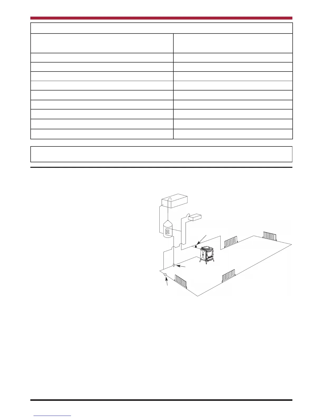
This diagram illustrates the basic principal of water
heating systems and must not be regarded as a
working drawing.
Fig.9
Pipe Thermostat
Injector Tee
Pump
INJECTOR TEE
Where the gravity and central heating circuits join
together to return to the stove we recommend the
use of an injector tee connection, situated as close
to the unit as possible. This type of tee encourages
a stable flow of hot water through both circuits and
helps to prevent priority being given to the stronger
flow, which is most commonly the pumped central
heating circuit. This way, there will be no shortage
of hot water to the taps when the heating is on.