person, but not authorized by STANLEY, the warranty will not
be valid..
LABELS ON TOOL
The following symbols are shown on the tool along with the
date code:
TECHNICAL INFORMATION
INTENDED USE
This appliance has been designed for individual use for
the cleaning of vehicles, machines, boats, masonry, etc, to
remove stubborn dirt using clean water and biodegradable
chemical detergents.
Vehicle engines may be washed only if the dirty water is
disposed of as per regulations in force.
Intake water temperature: See data plate on
the appliance.
f Intake water pressure: min. 0.1 MPa - max. 1 MPa.
f Operating ambient temperature: Above 0 °C.
The appliance is compliant with the IEC 60335-1 and IEC
60335-2-79 standards.
OPERATOR
The symbol illustrated in Fig. A identifies the appliance’s
intended operator (professional or non-professional).
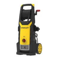
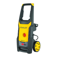
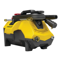
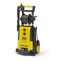
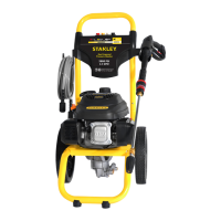
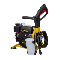
MAIN COMPONENTS (Fig. A)
1. Lance
2. Gun with safety catch
3. High pressure hose
4. Nozzle cleaning tool
5. Rotating nozzle kit
6. Nozzle
7. Adapter
8. Water lter
9. Detergent kit
10.Screws
11.Electric cable with plug
12.Wheels
13.Hose reel
14.Handle
15.Lever
16.Brackets
Starter device (19)
The starter device prevents accidental use of the appliance.
Caution! Safety devices:
Do not tamper with or adjust the safety valve setting.
f Safety valve and/or pressure limiting valve.The safety
valve is also a pressure limiting valve.
When the gun trigger is released, the valve opens and
the water recirculates through the pump inlet or is
discharged onto the ground.
f Thermostat valve (where fitted)
If the water temperature exceeds the temperature
set by the manufacturer, the thermostat valve
discharges the hot water and draws in an amount of
cold water equal to the amount of water discharged,
until the correct temperature is restored.
f Safety catch (21): prevents accidental spraying of water.
f Overload cutout: stops the appliance in case
of overload.
INSTALLATION (Fig. B)
Assembly
Warning! All installation and assembly operations must
be performed with the appliance disconnected from the
mains power supply.
The assembly sequence is illustrated in Fig. B.
Fitting the rotating nozzle
The rotating nozzle kit delivers greater washing power.
Use of the rotating nozzle may cause a reduction in pressure
of 25% compared to the pressure obtained with the adjustable
nozzle. However, the rotating nozzle kit delivers greater wash-
ing power due to the rotation of the water jet.
Electrical connection
Warning! Check that the electrical supply voltage and
frequency (V/Hz) correspond to those on the appliance data
plate (Fig. B8).
Use of extension cables: Use cables and plugs with “IPX5”
protection level. The cross-section of the extension cable
should be pro- portionate to its length; the longer it is, the
ENGLISH
8