BeiJing Starfire Control Technology Co.,Ltd WeChat:18901200180 QQ: 1908817881
6
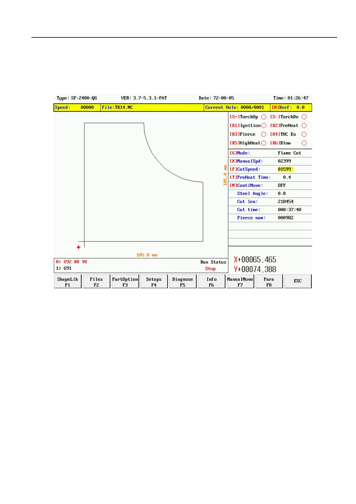
Chapter 2 main interface description
2.1 main screen button description
After starting up the system, as shown in the figure below:
Under the main interface, the key functions are as follows:
【F1】Gallery: enter the graphics library, most of which are available in sheet size and hole size. You can also enter the
nesting screen.
【F2】File: select local file, U disk file, file edit, file delete, file import export and other operations.
【F3】Part options: mirror, rotate, starting point, rotate correction, scale, segment selection, etc.
【F4】Process parameters: all parameters can be set here.
【F5】Diagnostic Settings: input/output diagnostics, system Settings, port customization, etc.
【F6】Graphic information: enlarge graphics, view punch points, and cut information display.
【F7】Manual: manually move the machine tool, reset system coordinates, return parameters, and select
breakpoints.
【F8】Modify parameters: it can modify common cutting parameters.
【G】Set cutting mode: press this button to switch the three modes of flame, plasma and demonstration.
【X】Manual speed: sets the manual movement speed.
 Loading...