EasyManua.ls Logo

Starfire SF -2100 - c - User Manual

Default Icon
24 pages
Print Icon
To Next Page IconTo Next Page
Loading...
1
catalogue
SF - 2100 - c fast operation manual ......................................................................... 3
The first chapter system operation panel ................................................................. 3
The second chapter main interface ........................................................................... 5
The third chapter cutting process .............................................................................. 6
Automatic cutting process diagram .............................................................................. 6
The first section selection processing graphics ........................................................... 6
3.1.1 gallery features ................................................................................................... 7
3.1.2 processing file selection ...................................................................................... 8
3.1.3 parts option function ......................................................................................... 10
The second section setting processing parameters .................................................. 11
The fourth chapter machining process ....................................................................... 14
4.1 to suspend operations ......................................................................................... 14
4.2 after suspend mobile perforation position or cutting position ............................... 15
4.3 the original track back processing ........................................................................ 15
4.4 breakpoints recovery and restore power .............................................................. 16
4.5 parts of functions ................................................................................................. 17
4.6 the edge of the thick plate perforation ................................................................. 18
The fifth chapter interface definition .......................................................................... 19
5.1 interface diagnosis and definition ......................................................................... 19
The sixth chapter Description of built-in height control function ................................. 20
6.1 System composition ............................................................................................. 20
Question and Answer IconNeed help?

Do you have a question about the Starfire SF -2100 - c and is the answer not in the manual?

Summary

Selection Processing Graphics

Gallery Function

Access system gallery features via F1 for viewing graphics.

Processing File Selection

Manage native, U disk files; perform edit, import, and export operations.

Parts Option Function

Configure machining for mirror, rotate, start point, and scaling.

Setting Processing Parameters

Machining Process Operations

Suspend Operations

Procedures for pausing operations due to system or external issues.

Change Perforation;Cutting Position

Adjust cutting or perforation position after system pause.

Original Track Back Processing

Steps to return to the original cutting path after a processing failure.

Breakpoint Recovery and Restore Power

System's capability to save and recover from power loss during processing.

Choose Section Code Function

Initiate processing from a specific section or piercing point.

Edge of Thick Plate Perforation

Method for edge perforation on thick plates during automatic cutting.

Interface Definitions

Pin Number Definitions

Detailed mapping of pin numbers to their respective interface functions.

Built-in Height Control Functions

System Composition

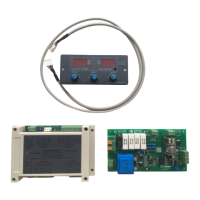
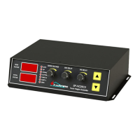
Overview of system components including control system and communication lines.

Parameter Description

Comprehensive explanation of machine operational parameters.

Wiring Definition

Electrical wiring diagram and explanation for system connections.

Fault Diagnosis

Guidance for troubleshooting communication line connectivity issues.

Automatic Cutting Height Adjustment

Procedures for adjusting cutting height during automated processing.

Software Upgrade Instructions

Overview

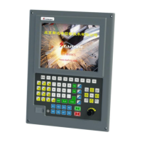
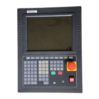
This document describes the SF-2100-C flame/plasma CNC system, a numerical control system designed for cutting processes. It covers the system's composition, operation, parameter settings, and maintenance features.

Function Description

The SF-2100-C is a CNC system primarily used for flame and plasma cutting operations. It provides comprehensive control over the cutting process, from graphic selection and parameter setting to actual machining and error recovery. The system integrates a built-in height control function to ensure precise cutting.

System Composition

The complete system comprises:

  • SF-2100C Numerical Control System: The main control unit with a display panel and function keys.
  • Communication Line: Connects the main control unit to other components. Users need to weld this line according to the required length.
  • SF-HC25J2 (or SF-HC25G0) Height Controller: Manages the torch height during cutting.
  • Split-Pressure Plate: Likely an interface board for various signals.

Important Technical Specifications

Parameter Settings (THC - Torch Height Control):

  • Built-in Height Adjustment: Can be enabled (1) or disabled (0). Default is 0.
  • Dead-band Voltage (0.1-10.00V): When the difference between the set arc voltage and actual value is less than this, the cutting gun height will not be adjusted. Default is 1.0V.
  • Sensitivity (1-10): Controls the adjustment range of the cutting gun. A higher value means a greater range. Default is 1.
  • Manual Up/Down Speed (0-100): Speed for manual height adjustment. Default is 200.
  • Cutting Up/Down Speed (0-100): Speed for automatic height adjustment. Default is 200.
  • INS Speed (0-100): Positioning rise rate. Default is 200.
  • Zero Low/High Enable (0/1): For the positioning switch. 0 for low level effective, 1 for high level effective. Default is 0.
  • Limit+ Low/High Enable (0/1): For the upper limit switch. 0 for low level effective, 1 for high level effective. Default is 0.
  • Limit- Low/High Enable (0/1): For the lower limit switch. 0 for low level effective, 1 for high level effective. Default is 0.

Interface Definitions (Pin Numbers and Functions):

  • X-axis Control:
    • Pin 1: X direction +
    • Pin 9: X direction -
    • Pin 2: X pulse +
    • Pin 10: X pulse -
  • Y-axis Control:
    • Pin 3: Y direction +
    • Pin 11: Y direction -
    • Pin 4: Y pulse +
    • Pin 12: Y pulse -
  • Communication & Power:
    • Pin 5: COM
    • Pin 13: RXD
    • Pin 6: TXD
    • Pin 14: 24+
    • Pin 7: (unspecified, likely ground or another signal)
    • Pin 8: 24-
    • Pin 15: (unspecified, likely ground or another signal)

Usage Features

1. System Operation Panel:

  • Function Keys (F1-F8): Context-sensitive keys with varying functions depending on the interface.
  • Page Up/Down (S↑/PgUP, S↓/PgDn): Used for navigating code interfaces and controlling torch movement (up/down) in manual/automatic modes.
  • Line Jump/Speed Control (F↑/HOME, F↓/END): Jumps to the first/last line in code, or speeds up/slows down operation.
  • Numeric Keys (1-9): For numerical input and selecting corresponding letter buttons (with "shift").
  • Directional Keys (X+, X-, Y+, Y-): For moving the cutting torch or cursor.
  • Enter Key: Confirms input values or selects projects.
  • ESC Key: Exits current interface or deselects.
  • Function Switch Buttons (IGNITING, PRCTRL, GAS, CUTOXY, PREHEA, CLOSE): Control specific functions like ignition, preheating, gas, cutting oxygen, perforation, and closing.
  • Shift Key: Used for inputting composite keys.

2. Main Interface:

  • F1 (Gallery): Accesses 24 common graphic libraries with predefined sizes and pore sizes.
  • F2 (Files): Manages native files, U disk files, and allows editing, import, and export.
  • F3 (Part Option): Configures machining parts (mirror, rotate, starting point, rotation correction, scaling).
  • F4 (Parameters): Sets all system parameters.
  • F5 (Diagnosis): Provides input/output diagnosis, system settings, storage file management, and I/O custom parameters.
  • F6 (Zoom In): Zooms graphics, views perforation, and displays cutting information.
  • F7 (Manual Move): Manual machine movement, coordinate system reset, and breakpoint selection.
  • G (Mode): Sets cutting mode (flame, plasma, demonstration).
  • X (Manual Speed): Sets manual movement speed.
  • F (Cut Speed): Sets automatic cutting speed.
  • T (Pier Time): Sets preheating time delay.
  • N (Set Kerf): Sets slot size before cutting.
  • Start/Pause/Stop: Initiates, pauses, or stops cutting.

3. Processing File Selection:

  • Gallery Function (F1): Allows selection from 24 graphic units. Directional keys move the cursor, and the Enter key confirms selection.
  • File Management (F2): Accesses files from hard disk or U disk.
    • F1 (Files): Displays hard disk file list.
    • F2 (USB): Displays U disk directory.
    • F3 (Edit): Edits the current cursor file.
    • F4 (Delete): Deletes the current cursor file.
    • F5 (Copy to USB/Native): Copies files between the system and USB drive.
    • F6 (New Folder): Creates a new folder.
    • F7 (OK): Confirms the current processing file and exits to the main interface.

4. Parts Option Function (F3):

  • F1 (StartP): Selects starting point.
  • F2 (Rotate): Rotation correction, including plate leveling.
  • F3 (Array): For simple discharge machining parts (NEST).
  • F4 (Scale): Scales processing parts.
  • F5 (Section): Chooses from any perforation PM processing.
  • F6 (EditFil): Views and modifies the current cut file.
  • F7 (Revert): Cancels operations and restores graphics to original state.
  • X (X Mirror): Mirrors graphics along the X-axis.
  • Y (Y Mirror): Mirrors graphics along the Y-axis.

5. Setting Processing Parameters:

  • Cutting Pattern [G]: Switches between flame, plasma, and demonstration modes.
  • Cutting Speed [F]: Modifies numerical cutting speed.
  • Manual Speed [X]: Modifies numerical manual movement speed.
  • Slot [N]: Modifies slot size.
  • Preheat Time Delay [T]: Modifies preheat time delay.

6. Machining Process:

  • Suspend Operations: During processing, if flame failure, arc voltage interruption, or other issues occur, the system can be paused.
    • F1 (BACKWARD): Moves cutting nozzle back along the trajectory.
    • F2 (FORWARD): Moves cutting nozzle forward along the trajectory.
    • F3 (RETURN): Returns cutting nozzle to the starting point.
    • F4 (N-PIERCE): Selects any perforation point to cut.
    • F5 (ZOOMIN): Graphic magnification.
    • F6 (DELAY+): Increases preheating time by 10 seconds.
    • F7 (DELAY END): Ends preheating, skipping remaining preheating time.
  • Change Perforation/Cutting Position After Pause:
    • Original Path Return (Only Return): Returns to adjust the starting point at G00 speed.
    • Cut On Return Path (Cutting Return): Cuts along a straight line from the current position to the starting point.
    • Start Cutting Here (Offset Cutting): Perforates first, then continues processing from the adjusted current coordinates.
  • Original Track Back Processing: For cases where cutting fails to penetrate, allowing the system to trace back.
    • F1 (BACK): Performs original track back.
    • F2 (DEMO): (Unspecified, likely for demonstration or simulation).
    • F3 (GO BACK): (Unspecified, likely another form of return).
    • F4 (TO PIERCE): Selects a piercing point.
    • F5 (ZOOM IN): Graphic magnification.
    • F6 (HEAT ADD): (Unspecified, likely related to heating).
    • F7 (HEAT DN): (Unspecified, likely related to heating).
  • Choose Section Code Function (F4): Allows starting processing from an arbitrary section or piercing point in the program.
  • Edge of Thick Plate Perforation:
    • Moves the cutting torch to the plate edge.
    • Starts preheating, then cuts along a straight line at the selected speed.
    • Uses edge notch parameter (set to 1).
  • Location Perforation: System positions for inner hole perforation.
  • Select Edge of the Hole: Adjusts cutting torch position to the outer limits of the steel plate using directional keys, then starts preheating and cutting.
  • Don't Perforate: System runs directly from the current perforation position, skipping to the next hole.

7. Automatic Cutting, Adjust Height:

  • [1]/[2]: Increase/decrease arc voltage setting value.
  • [4]/[5]: Increase/decrease positioning delay time.
  • [6]: Performs cutting gun positioning test.
  • THC Status Signals: Displays "automatic," "rising," "falling," "origin," "upper limit," "lower limit," "arcing" to indicate height control status.

Maintenance Features

1. Fault Diagnosis:

  • If the communication line is connected incorrectly or not connected, the system will display an error message on the automatic screen. Troubleshooting the communication line is necessary for normal operation.

2. Software Upgrade Instructions (Appendix 1):

  • Function: System can be upgraded via a U disk.
  • Upgrade Files: Copy STARTCNC.EXE to the U disk.
  • Operation Steps:
    1. Insert the U disk.
    2. Press the pause button on the front panel.
    3. Turn on the power.
    4. Release the button when the upgrade interface appears.
    5. The system automatically performs the upgrade.
  • End of Upgrade:
    • Success: "upgrade successful!" and a buzzer sound.
    • Failure: "upgrade failed!" and continuous buzzer sound.
  • Start New Program: Turn off power, remove U disk, turn on power again. The new version number will be displayed.
  • Notes for Unsuccessful Upgrade:
    • U disk must be FAT or FAT32 format (FAT recommended).
    • Upgrade file name must be STARTCNC.EXE.
    • If the process returns to the main interface without completion or other accidents occur, check file name and U disk format, then retry.

This comprehensive description highlights the SF-2100-C's capabilities as a robust and user-friendly CNC system for flame and plasma cutting, emphasizing its operational flexibility and integrated height control for precision.

Starfire SF -2100 - c Specifications

General IconGeneral
BrandStarfire
ModelSF -2100 - c
CategoryController
LanguageEnglish

Related product manuals