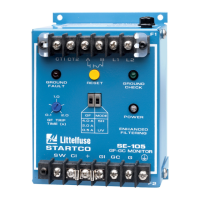
Startco Engineering Ltd. Page 11
SE-105 Ground-Fault Ground-Check Monitor Rev. 9
Pub. SE-105-M, November 24, 2005.
5. TECHNICAL SPECIFICATIONS
Supply:
ac ........................................ 120 or 240 Vac (+10,
-45%), 50/60 Hz, 10 VA
ac/dc ................................... 120 Vdc (+40, -8%), 5W
120 Vac (+10, -29%),
47 to 440 Hz, 5 VA
NOTE: Voltage between supply terminals (L1, L2) and
ground terminal (G) must not exceed 300 Vac
continuous or 1,250 Vac under transient
conditions.
Dimensions:
Height................................. 150 mm (5.9″)
Width.................................. 109 mm (4.3″)
Depth.................................. 100 mm (4.0″)
Shipping Weight........................ 1 kg (2.2 lb)
Environment:
Operating Temperature ...... -40 to 60°C
Storage Temperature .......... -55 to 80°C
Humidity ............................ 85% Non-Condensing
Ground-Fault Circuit:
CT Ratio............................. 200:5
CT Input Burden ................ 0.02 Ω
Trip Level
(1)
....................... 0.5, 2.0, or 4.0 A
Frequency Response .......... 25 to 400 Hz,
25 to 110 Hz with
Option H
Trip Time ........................... 0.1 to 2.0 s
Thermal Withstand
(1)
......... 200 A Continuous,
2,500 A for 2 s
Trip-Level Accuracy .......... +10, -20%
CT Lead Resistance Limit
(2)
0.5 A Trip Level.......... 2 Ω
2 A Trip Level............. 5 Ω
4 A Trip Level............. 5 Ω
Trip-Time Accuracy........... 10%
Operating Mode ................. Latching
(1)
Currents referred to primary of CT200 for
prospective ground-fault currents less than 4,000 A.
(2)
Typical maximum CT lead resistance to meet
specified trip-level accuracy.
Ground-Check Circuit:
Open-Circuit Voltage......... 12 Vdc
Output Impedance.............. 240 Ω
Nominal Loop Current....... 25 mA
Induced-ac Withstand ........ 25 Vac Continuous,
120 Vac for 3 s
Fuse Rating (F2)................. 0.5 A, 250 Vac,
Time Delay
Fuse Part Number............... Bussman MDA-1/2,
MDL-1/2 or
Littelfuse 313.500
Pull-in Time ....................... 1.5 s
Trip Time ........................... 0.2 s (GC open),
0.5 s (GC to G short)
Trip-Time Accuracy .......... +10, -30%
GC-Loop Trip Resistance .. 40 ± 10 Ω
Operating Mode ................. Non-Latching,
Latching with Option L
Output Relay:
CSA/UL Contact Ratings... 1 mA to 4 A Resistive,
240 Vac or 28 Vdc
Supplemental Contact Ratings:
Make/carry 0.2 s ......... 10 A
Carry continuous......... 4 A
Break:
dc........................... 20 W resistive,
10 W inductive
(L/R=0.04 s)
ac ........................... 960 VA resistive,
700 VA inductive
(PF=0.4)
Subject to maximums of 4 A and 240 V (ac or dc)
Contact Configuration........ N.O. (Form A)
Fuse Rating (F1) ................ 4.0 A, 250 Vac,
Time Delay
Fuse Part Number .............. Bussman MSL-4 or
Littelfuse 313.004
Operating Mode ................. UV (Undervoltage/Fail-
Safe) or SH (Shunt
Trip/Non-Fail-Safe)
Remote Indication:
+ ......................................... 12 Vdc
GI/CI.................................. Current Sink,
560 Ω Internal
Optional RK-13 Module:
Contact Ratings..................... 100 mA, 120 Vac
Contact Configuration........... N.O. (Form A)
Reset Input ............................ 24 to 120 V (ac or dc),
Isolated
PWB Conformal Coating............. MIL-1-46058 qualified,
UL QMJU2 recognized
Certification .............................. CSA, Canada and USA
LR 53428
USC
R
Australia